I want to mod my (MS2357-C) MS2/ 3.57 PCB for flat-shift and launch control. So far, my MS has been modified for GM HEI ign control, flex fuel, boost control (output through js11) and knock sensor input (through pad13 to js4).
The instructions said to build a circuit to supply reference input (which can be built to either trigger on + or - input depending on how you build it) then it said to jumper input to JS7 and to set the proper calibrations
So, the idea I have in my head is to...
Step A: build this circuit for "low input" on a separate cheese board (since my 3.57 pcb has no proto area)

Step B: connect the two switch wires to a clutch pressure switch.
Step C: connect this other end of the switch wire to pin10 of the MS2 daughterboard (PEO/ JS7) for input.
A quick visual of what I plan...
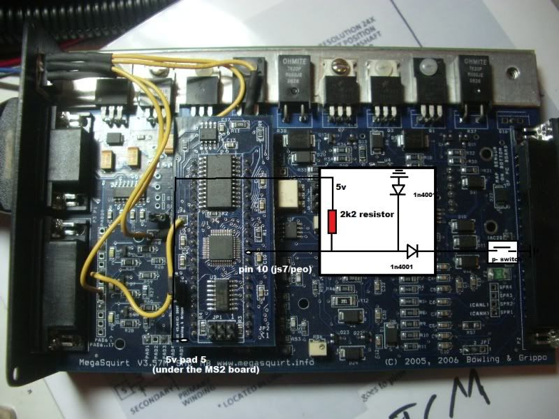
(note: The picture is abstract. The circuit is grounded (-) through the MS2 and NOT the frame of the car. It was just easier to draw this way)
The instructions were garbled together with steps for a "map-switching" mod, so Im not 100% if this configuration is correct. Have any of your experimented with this before?
The instructions said to build a circuit to supply reference input (which can be built to either trigger on + or - input depending on how you build it) then it said to jumper input to JS7 and to set the proper calibrations
So, the idea I have in my head is to...
Step A: build this circuit for "low input" on a separate cheese board (since my 3.57 pcb has no proto area)

Step B: connect the two switch wires to a clutch pressure switch.
Step C: connect this other end of the switch wire to pin10 of the MS2 daughterboard (PEO/ JS7) for input.
A quick visual of what I plan...

(note: The picture is abstract. The circuit is grounded (-) through the MS2 and NOT the frame of the car. It was just easier to draw this way)
The instructions were garbled together with steps for a "map-switching" mod, so Im not 100% if this configuration is correct. Have any of your experimented with this before?

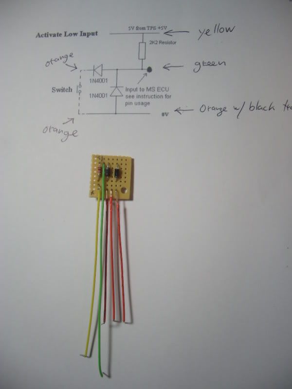
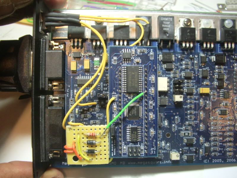
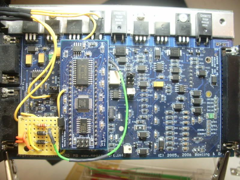
 ) with a 1/4 watt rating and went with that. Heres the final switch input circuit with the wire-color legend...



Comment