Announcement

Collapse
No announcement yet.

rocker arms...

Collapse
X
 
  • Filter
  • Time
  • Show
Clear All
new posts

  • #46
    Spent a little time on this today, and the wipe pattern is too far to the exhaust side by 4mm. Ideally, the same height rocker pedestal would be used but the rocker bolt would move backwards away from the valve 4mm. This is a viable solution only if offset sleeves are used and smaller-diameter rocker arm bolts are used. Getting a full 4mm out of an 8mm bolt though...not gonna happen that way.

    Using the stock 3500 pedestals, an LS1 rocker arm will strike the pedestal at 0.510" of valve lift. This is a fixable problem.

    Dropping the rocker arm pivot down could work, but causes other issues due to the location of the pushrod cup, which is just as important as the valve tip. Also, dropping the pivot down far enough to pull the tip 4mm is *probably* unworkable.

    Reshaping the rocker arm tip would work-but then will change the ratio of the rocker arm. Could possibly end up with 1.68 ratio, which isn't much gain, not really enough to justify the work involved.

    Obviously changing the valve angle is possible and would work fine, but again...work vs gain is low.

    Comment


    • #47
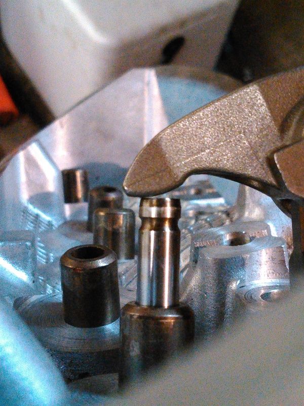
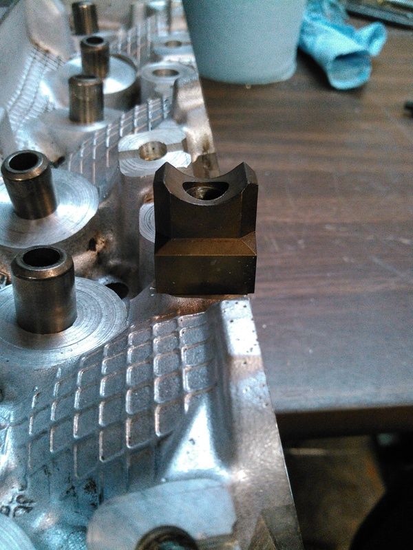
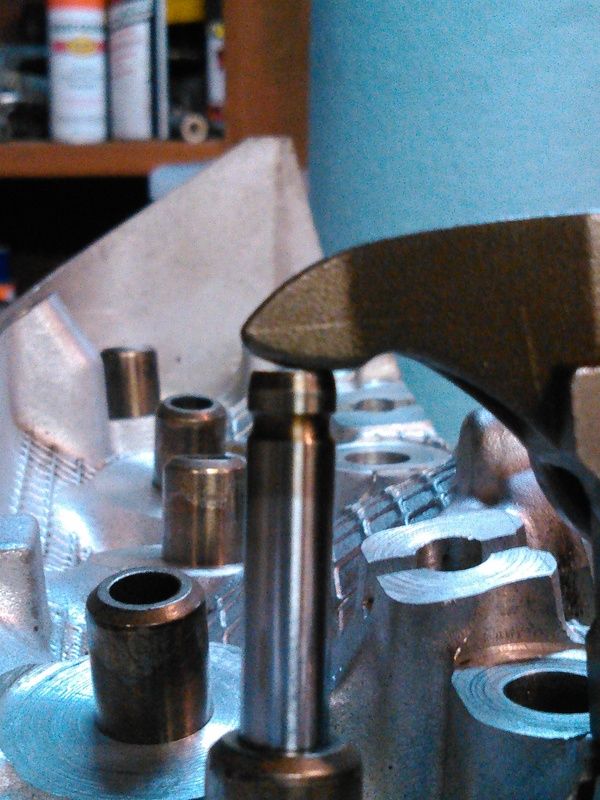
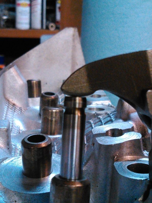
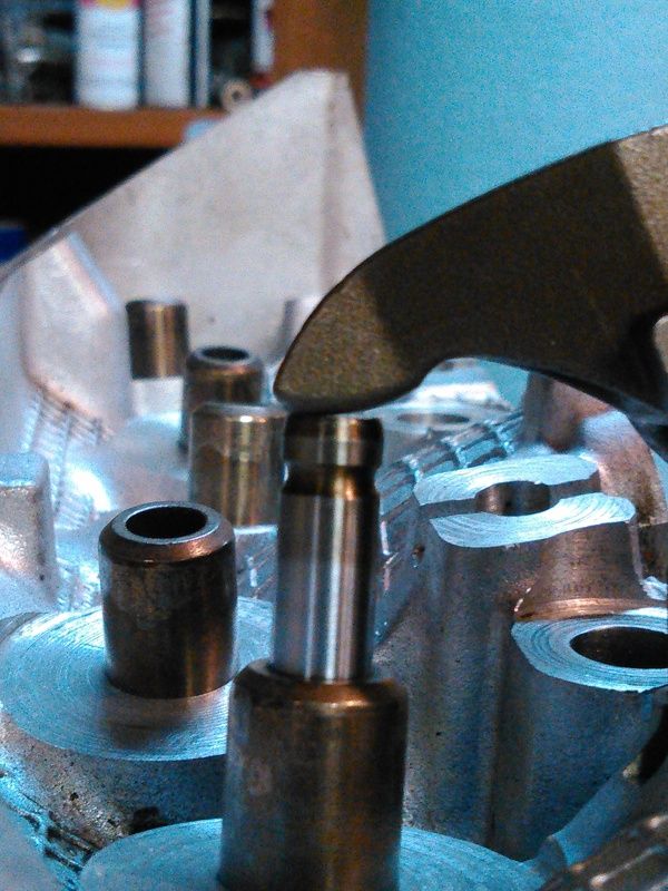
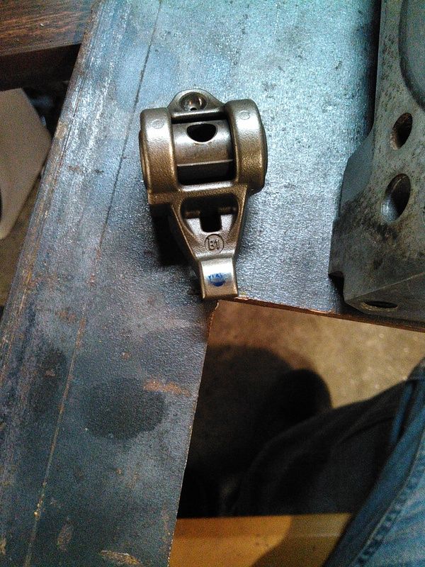
      Here are some photos of the rocker geometry-I'll have to make new offset trunnions for these to work for me. The tests were done from 0 lift to 0.510" lift, because the rocker hits the support stand at 0.510" lift.

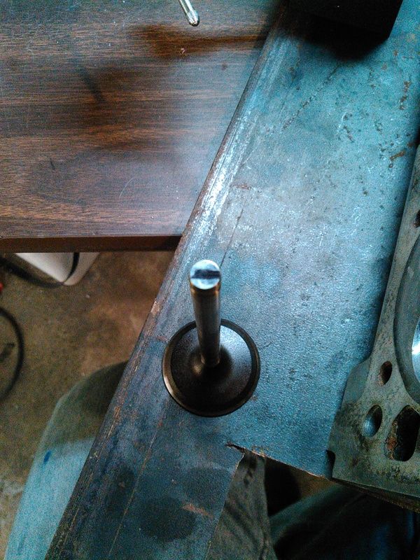
      Contact pad of the rocker arm itself:


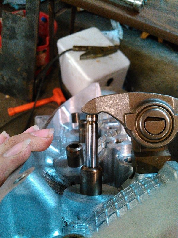
      Wipe pattern on valve stem (all the way to the left side...)


      Zero lift:


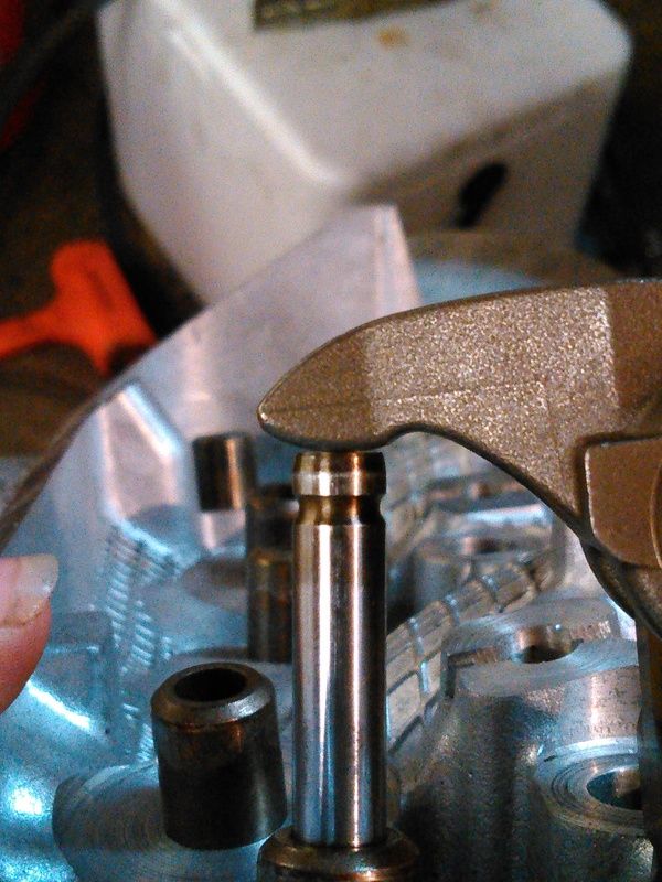
      0.400" lift:


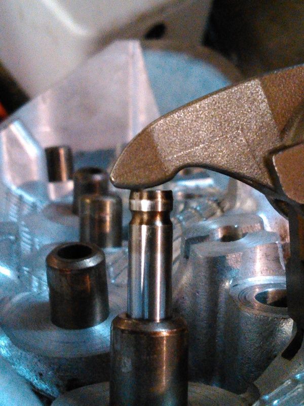
      0.510" lift:


      Rocker fulcrum really needs to move away from the valve about 140 thou, I think. More testing needed. Hopefully I can simply make an offset trunnion, modify the pedestal, and get it pushed back far enough to work and still bolt-on to the heads without modifying the cylinder head.

      Comment


      • #48
        Round off the nose of the rocker?

        Sent from my XT1080 using Tapatalk
        '86 Grand National

        Comment


        • #49
          That may also work, but the nose isn't solid so there is only so much material there to remove.

          Comment


          • #50
            Maybe weld the inside to bolster the material? And some backyard hardening?

            Sent from my XT1080 using Tapatalk
            '86 Grand National

            Comment


            • #51
              Nuh-uh. I have full heat treat capabilities here, and I would be skeptical since I do not know the actual alloy that I'm working with...so it's impossible to formulate a heat treat procedure that would be repeatable.

              However....

              I don't need to re-drill the holes in the cylinder head, just slot the holes in the rocker pedestal and the trunnion. They don't have to move much.

              The wipe pattern is pretty wide still but it's centered up over the valve tip, so once they're positioned fore-and-aft, I can adjust them up and down (looks to me like up slightly would help, and up is the easy way to go-shims) and get the geometry dialed in.

              This is the stock position, pushing it back 0.100" got me close on the wipe pattern.


              This is what the rocker tip looks like-Much better!

              Zero Lift:


              0.250" lift:


              0.510" lift:


              Now, it's not correct yet but the pattern is well centered, just wide. It doesn't encroach on the outside 0.020" of the valve stem though. Technically it's usable. In practice, you'd loose 0.012" of valve lift if you didn't shim the rocker UP the required amount. If slotting the rocker arm hole is workable then it is possible to get the rocker arm in the correct location, I think.

              Comment


              • #52
                What about LS3 roller tips and swap out the trunions?

                Sent from my XT1080 using Tapatalk
                '86 Grand National

                Comment


                • #53
                  Still going to require moving the rocker stand back, as well as probably not being cheaper than buying purpose-made rockers. And it's a 1.8 ratio rocker, IIRC.

                  Comment


                  • #54
                    Crude editing, and without a similar picture to compare to the roller tip, and I think they are also available in 1.7 as well. Used the grid lines in paint to get somewhat close-ish to scale.

                    You still think there will be issues using the same placement?
                    Attached Files
                    '86 Grand National

                    Comment


                    • #55
                      You're making a lot of assumptions in your drawing, and you still have to modify the rocker stands. It's possible but I'd be skeptical at best.

                      I just stuck a 1.88" 5.3L LM7 valve in the head, it's quite a bit longer and doesn't sit all the way down on the seat, but it worked for the "longer valve" approach to fixing the geometry completely.

                      With the factory fitted valve, factory 3500 rocker stand, and factory fitted rocker arm, maximum valve lift is 0.580", NOT the 0.700" lift that is mentioned earlier in this thread. This is the limit imposed by the rocker stand...the rocker actually hits the stand. At 0.590", the valve spring retainer its the valve stem seal. Still more than I need so not an issue for me.

                      With the factory fitted valve, factory height 3500 rocker stand, and LS1 rocker arm, an offset dowel (think cam pin bushing, just longer) can be used to move the rocker arm back away from the valve stem to get it positioned in the right spot. Just means drilling the rocker stand and rocker trunnion to 10mm and making the offset 8mm to 10mm dowel pin would work. Rocker arm needs to come down, or valve stem needs to get longer, according to the suggestions here. Either shorten rocker stand or lengthen valve tip.

                      With the 5.3L valve, factory 3500 rocker stand, and LS1 rocker arm pushed back, the valve geometry is as close as it'll get to working over the widest range, without actually cutting something up. The valve stem is a little *too* long, as the rocker tip is pushing on the side of the valve when the valve is "on the seat", but over the motion range the valve tip geometry is good. Maximum usable lift in this arrangement was 0.690". The valve is not anywhere close to fitting on the stock seat, and once turned down to actually fit the valve tip would be even higher, making the closed-valve geometry even worse...this valve is too long to really work, was only good for proof of concept.

                      If I was to make offset dowels, drill the rocker stands, and drill the LS1 rocker trunnions, AND fit a slightly longer valve stem, (approx 0.080") it could be made to work, and even the pushrod side works out well within acceptable for the cam lobe lift I will use.

                      I do not have a milling machine here that I could use to shorten factory stands but if I did, and I was willing to accept that ~0.510" lift was the maximum I could get, then yes, it would be possible to get proper geometry without changing the valve or spring package. Technically, a spare set of rocker stands and a few LS1 rocker arms could be modified into a bolt-on 1.7 ratio rocker solution, but you would be limited on valve lift to 0.510" maximum.

                      Curiosity satisfied!

                      Comment


                      • #56
                        From my searching, I've found that there are full rollers with a 8mm bolt, listed for LS6 mainly. I'm not sure how you arrived at a max of 510 for valve lift? From my perspective the OEM rocker tip is too flat and appears to introduce too much side loading on the valve and guide, which I don't like. You can see the gaps on either side. The flatter profile of the rocker tip appears to cover a broader range than with a roller. I don't have the resources you have but I may try to score a 1.7 ls6 rocker with the 8mm bolt and find out for myself. I'm happy you're satisfied. I'm not, though. lol

                        Sent from my XT1080 using Tapatalk
                        '86 Grand National

                        Comment


                        • #57
                          Also, if clearancing the boss is necessary, I have no problem with that especially since geometry could be improved and wear reduced.

                          Sent from my XT1080 using Tapatalk
                          '86 Grand National

                          Comment


                          • #58
                            The lift limit is 0.630 on 3500 heads, with stock valve stem seals and valve retainers, before the valve retainer hits the valve stem seal. The 0.510" lift limit is because the LS1 rocker hits the pedestal. The stock 1.6 ratio rocker arms hit the pedestal at 0.580". ALL LS rocker arms use 8mm bolts, and the bolts for LS1 heads are too short-you need 3500 rocker bolts.

                            The drilling and bushing is to MOVE the rocker away from the valve, to get the geometry close to right. Then you need to move the rocker pivot down, or the valve tip up, to finish getting it right. Moving the valve tip up means you can't just bolt-and-swap these with standard arms later, so moving the pivot down would mean stock parts could be put back on later if the "works" method is used.

                            Roller tip rocker does not help with side loading on the valve if the valve geometry is correct. It will not make fitting the LS1 type rocker any easier, just more expensive.

                            The rocker wipe pattern SHOULD be wide with a rocking tip like this, the radiused tip has to "rock" across the valve, and when the geometry is correct, the radius of the tip actually does rock across the valve-when the valve is closed, the inside edge of the rocker tip rests on the top of the valve, and as the valve is opened, it rocks smoothly across the top of the valve and does not side-load the valve. It does not and should not slide across the valve at all, the force is straight down and so there is no side loading IF the geometry is correct and the lift does not exceed the geometry-In this case, to keep the ideal geometry lift is limited to 0.500" anyway, going over does start to slide the tip back across the valve.

                            If the rocker geometry is not correct then the rocker tip SLIDES across the valve and this side-loads the valve. Roller-tip valves would change this from sliding to rolling friction but would still load the valve sideways some small amount.

                            The "correct" way to fix this is weld the rocker bolt holes in the head solid and re-drill them, and mill the rocker boss down 0.080". This is a one-way trip.

                            The "works" solution means disassembling the rocker arm (requires a press) grinding the bolt hole in the trunnion into a oval slot, milling the hole in the 3500 rocker stand larger diameter and off-center of the existing hole and it is a powder-metal rocker stand and is a deep hole, so carbide tooling and a milling machine would be needed to get it straight. A drill press will not work for this. An offset bushing with ID 8mm and OD the size of the new offeset hole in your rocker stand would need to be made. Then you need to either shorten the rocker stand, or have custom longer stem valves made.

                            It can be made to work but it is not worth the trouble unless you are building a racing engine. I went through all the trouble to make a plastic rocker trunnion and rocker stand the correct dimensions and proper offset to do it, and it *does* work, but for my 300HP truck engine it's not worth the effort or time to continue with it.

                            Comment

                            Working...
                            X