Originally posted by veekuusi
View Post
-
you can machine an o-ring groove around the hole, and then make a plate that catches on the accessory bolt holes on the head with an AN fitting on it where the freeze plug hole is. -
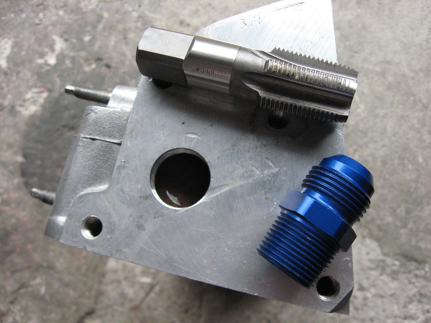
NPT 3/4 x 14 and AN -12Originally posted by bob442 View Post
Mission impossible.
You can not make the thread deep enough, the tap bottoms.
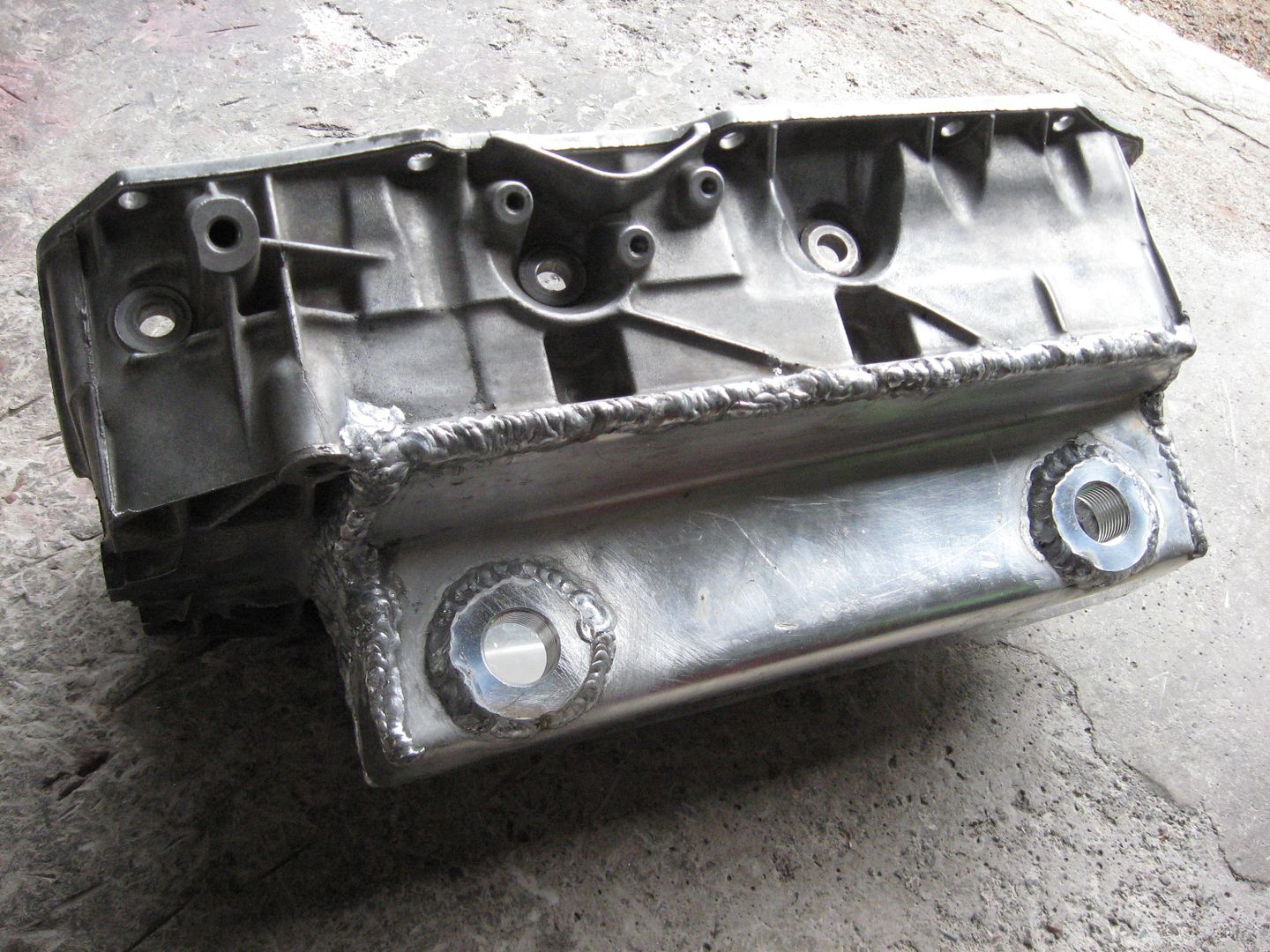
I have to weld the fitting to the head.
When you are talking about cylinder heads, best welding is no welding at all.
But what can you do?
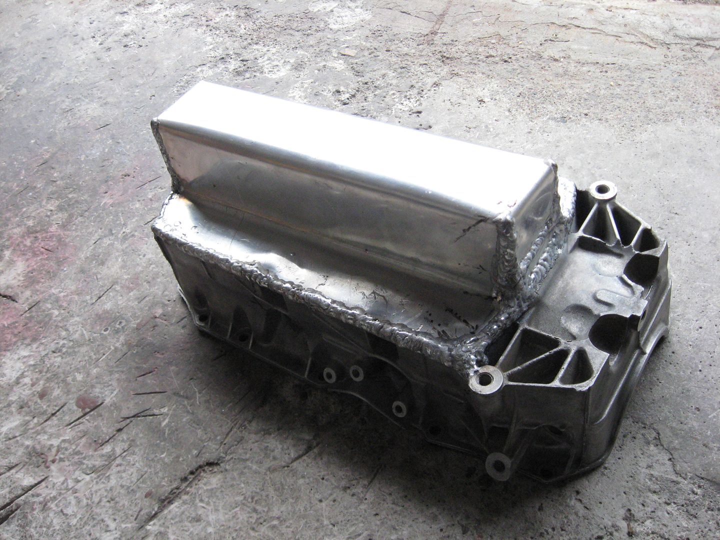
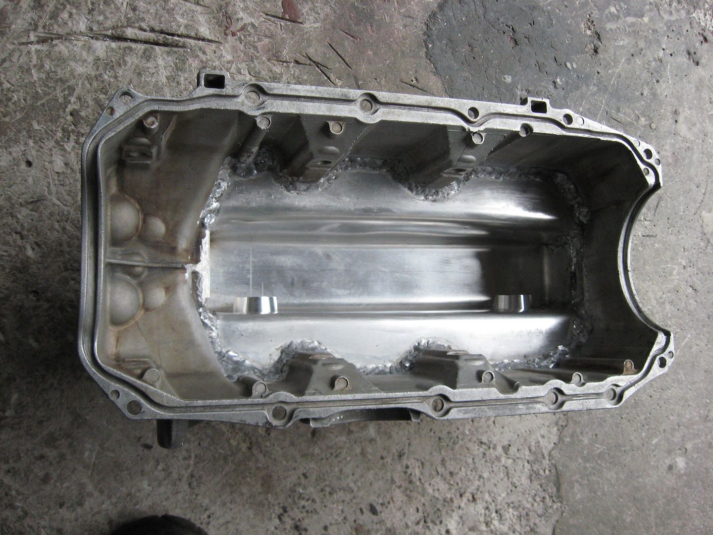
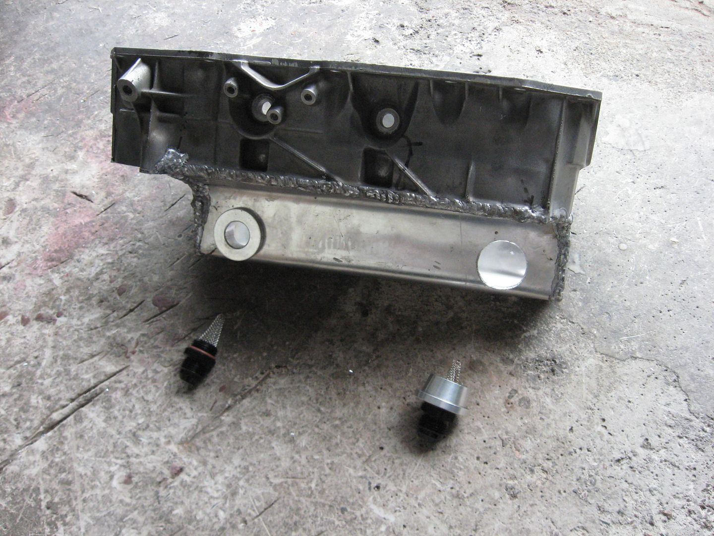
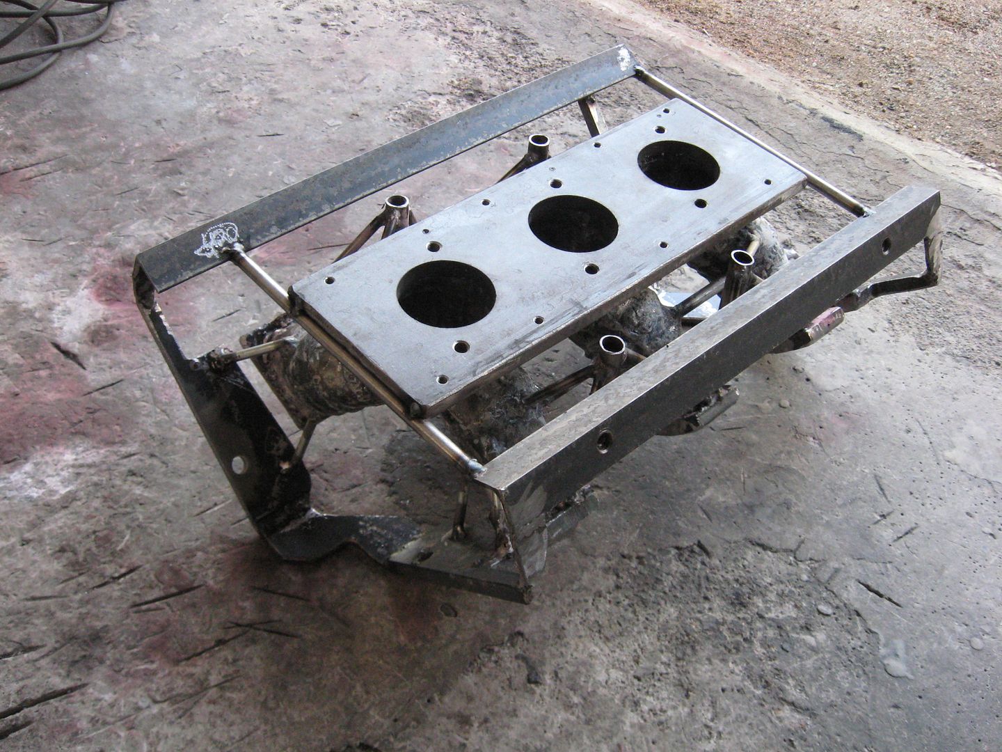
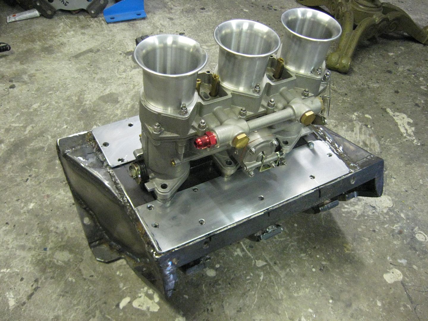
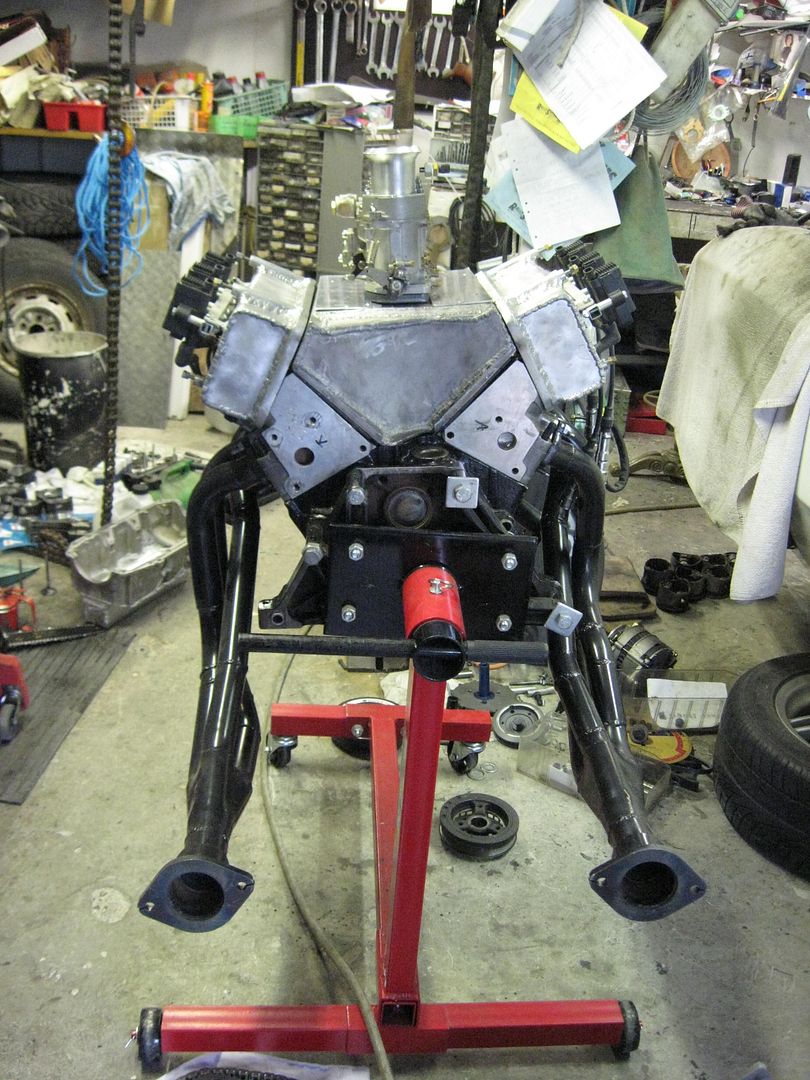
Also I made some modifications to the oil sump.
 Last edited by veekuusi; 07-07-2012, 11:31 AM.
Leave a comment:
-
they would have to be, either that or they would need a very good machinist and some huge AN fittings.Leave a comment:
-
you'll need to use regular pipe fittings, or an adapter instead of AN fittings going into the head, because AN fittings need a conical seat to seal to.Leave a comment:
-
Yes, AN fittings sounds and propably looks even better.Originally posted by bob442 View Post
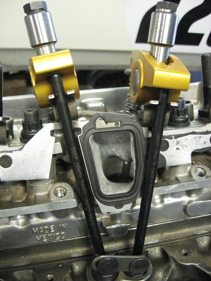
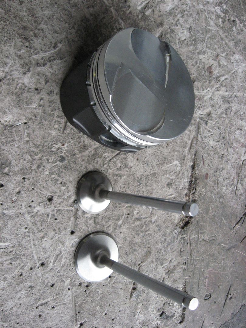
Comp Cams push rods.No need for special order (custom).
6.200" intake
6.400" exhaust
Very important that the roller tip is in the right position to valve stem.
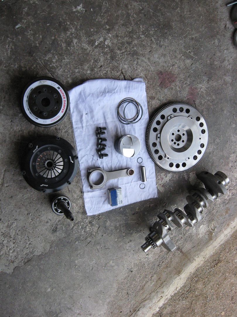
Bottom end of the engine goes tomorrow to machine shop for balancing.
They will balance it with the clutch , but without ATI damper.
 Last edited by veekuusi; 06-10-2012, 10:31 AM.
Leave a comment:
-
would it not be easier and cleaner, and probably seal better to tap out the frost plugs and thread some aluminum pipe? use pipe threads or get them tacked into place once they are tight..? or maybe some nice AN fittings and SS line...Originally posted by veekuusi View PostLeave a comment:
-
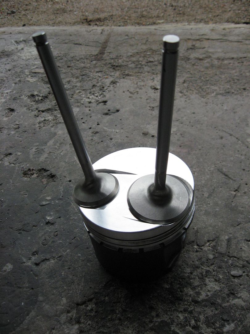
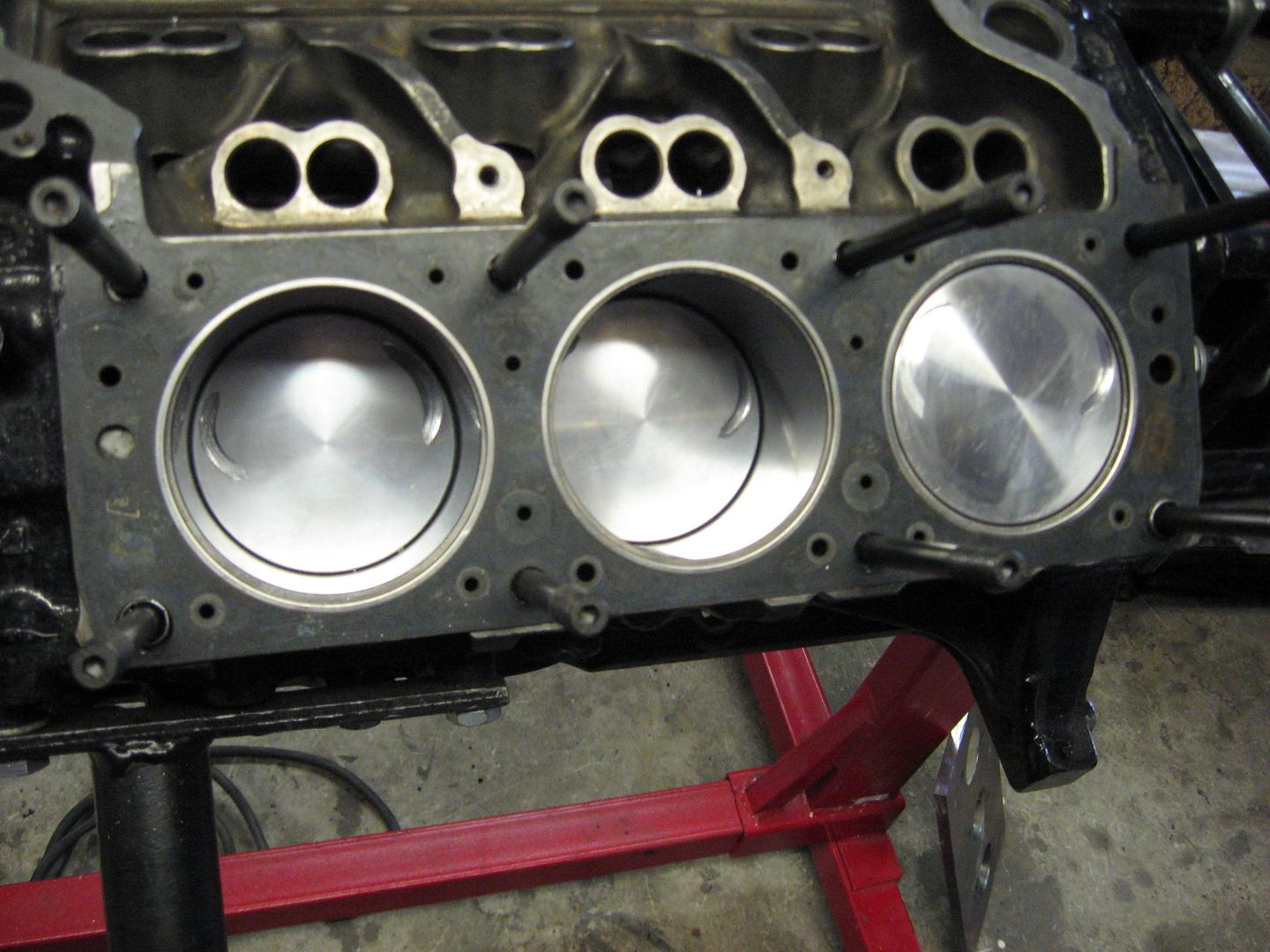
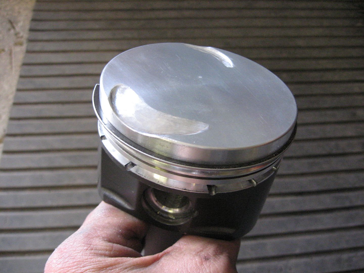
Some pictures of pistons.
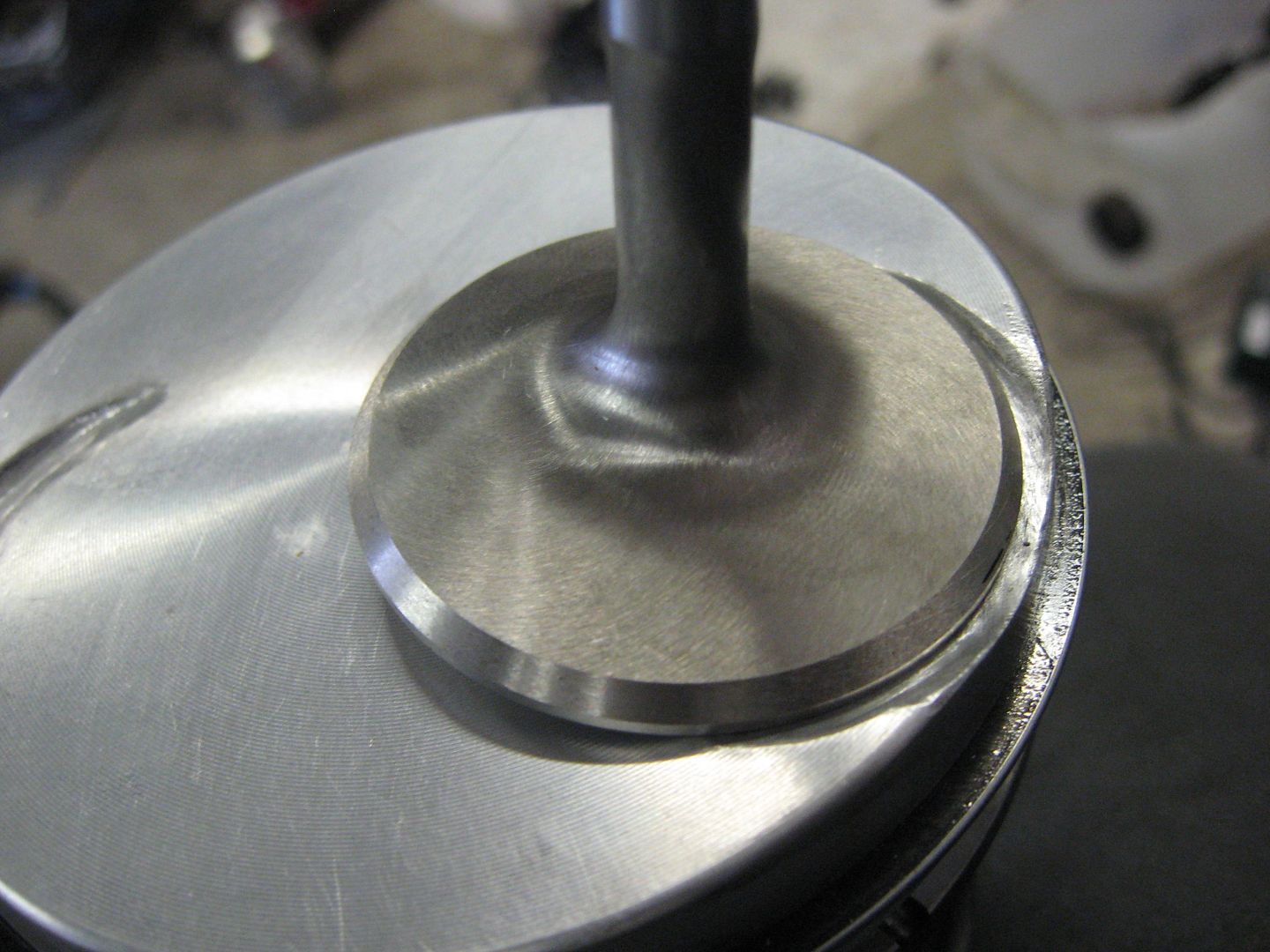
Valve reliefs in final look.
The red thing in the backgroud is a tool to hold the piston
while machining it.
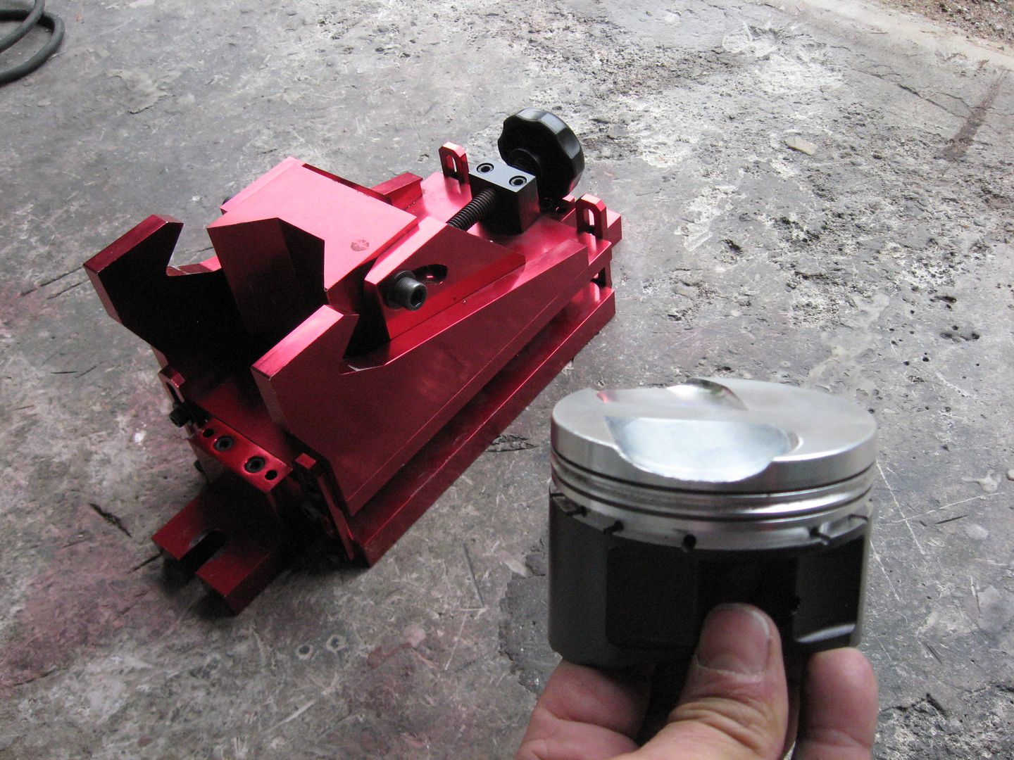
There is only 3 mm of material above the piston top ring.
But we think it is OK.
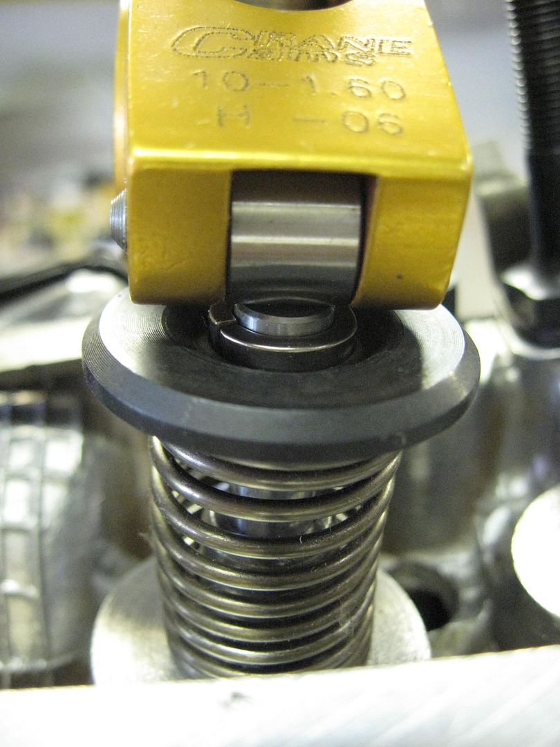
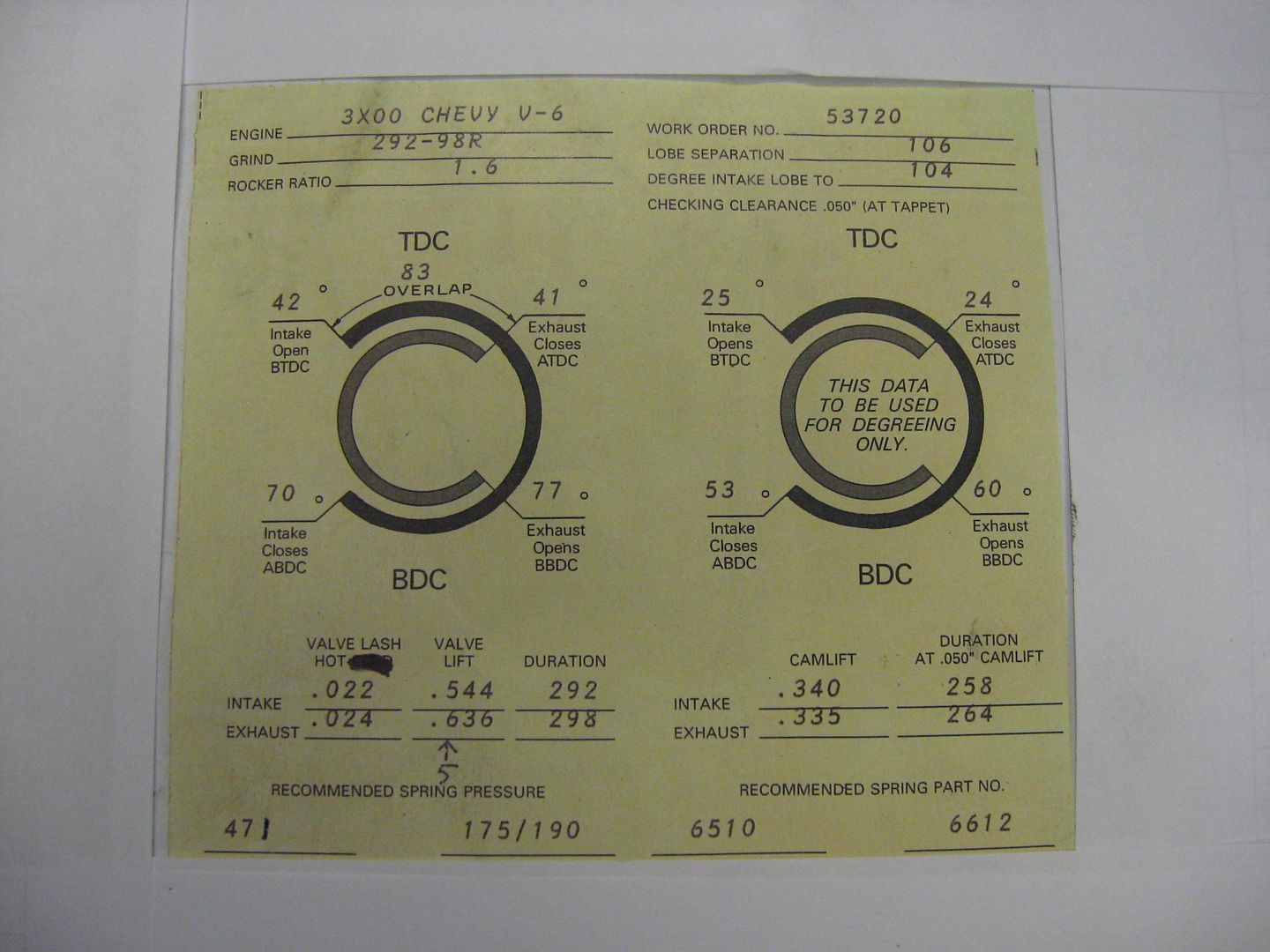
And some numbers of the camshaft that I am using.
It is funny , the valve lift is calculated wrong in the cam card.
It should be 13.2 mm , not 13.8 mm that is written in the card.
The push rods are angled, it changes the numbers.
Leave a comment:
-
Very good question.Originally posted by Superdave View Post
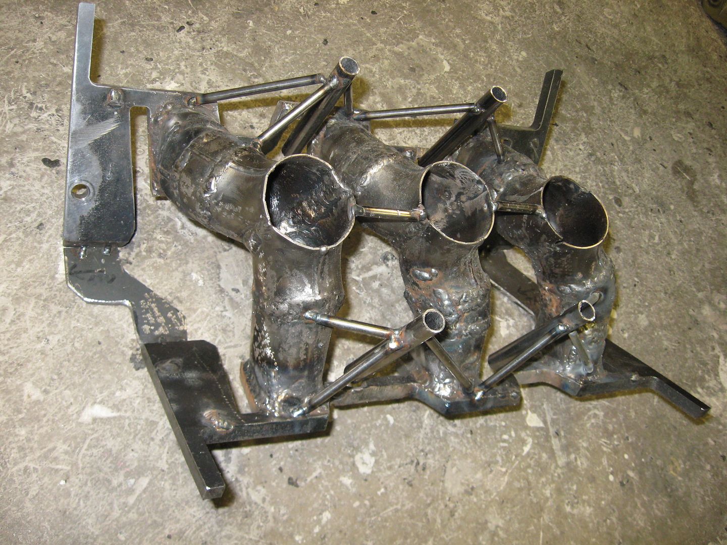
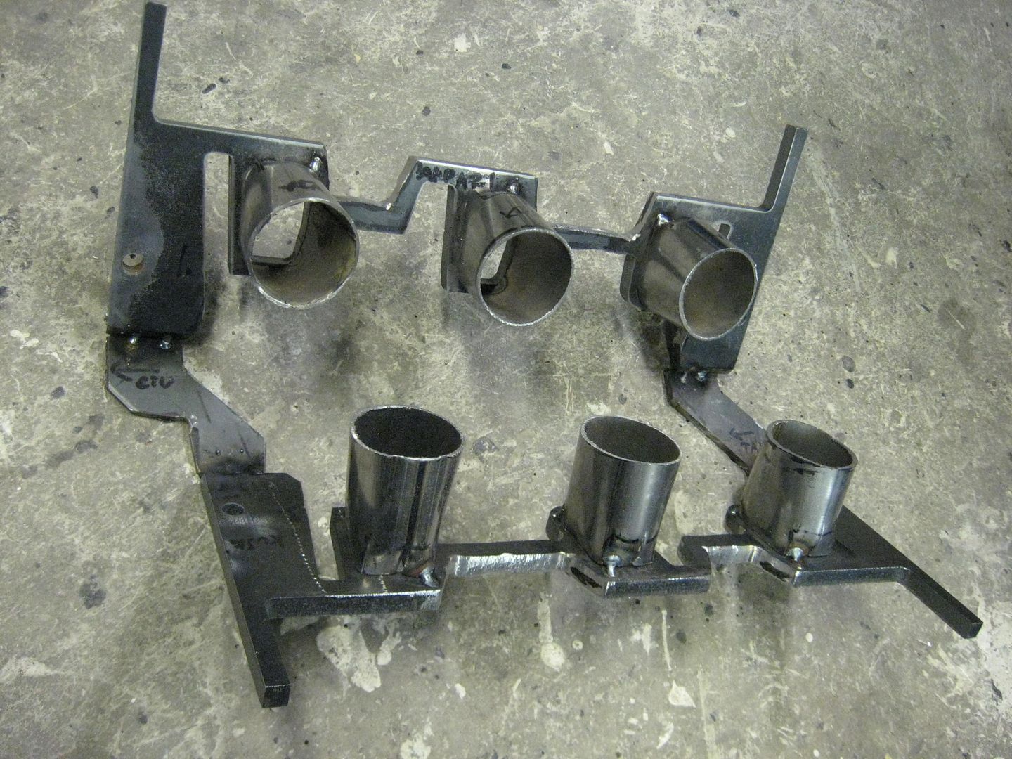
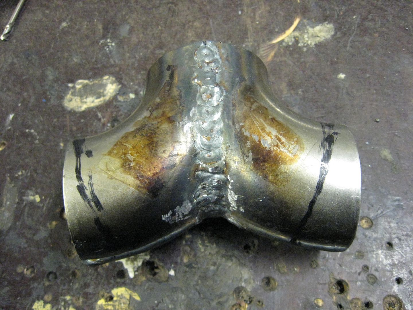
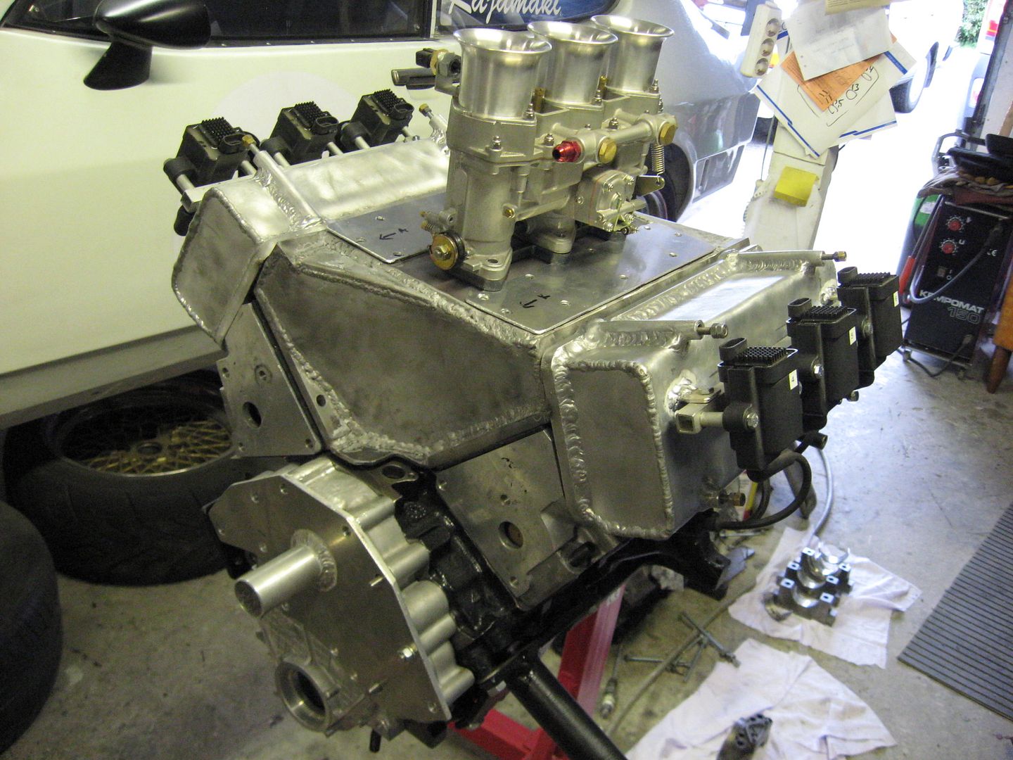
I am thinking of welding a pipe to the front end of both heads.
Thats where the coolant water comes out of the heads
and goes to radiator.
Allready trained some tig-welding to a spare head.
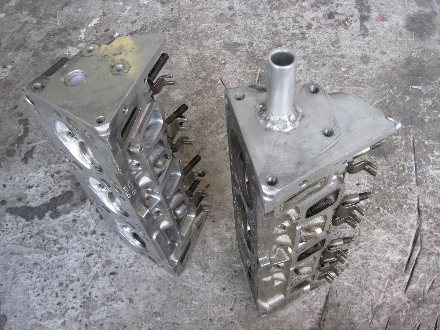
Only problem is that the pipe is not in the highest point of a head.
It leaves space for air bubbles.
I think there is a similar system in 3500 heads.
Although I have never seen a 3500 head.Last edited by veekuusi; 06-28-2012, 11:19 AM.Leave a comment:
-
Nice work but what are you doing with the coolant crossover from head to head?Leave a comment:
-
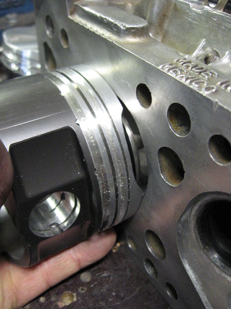
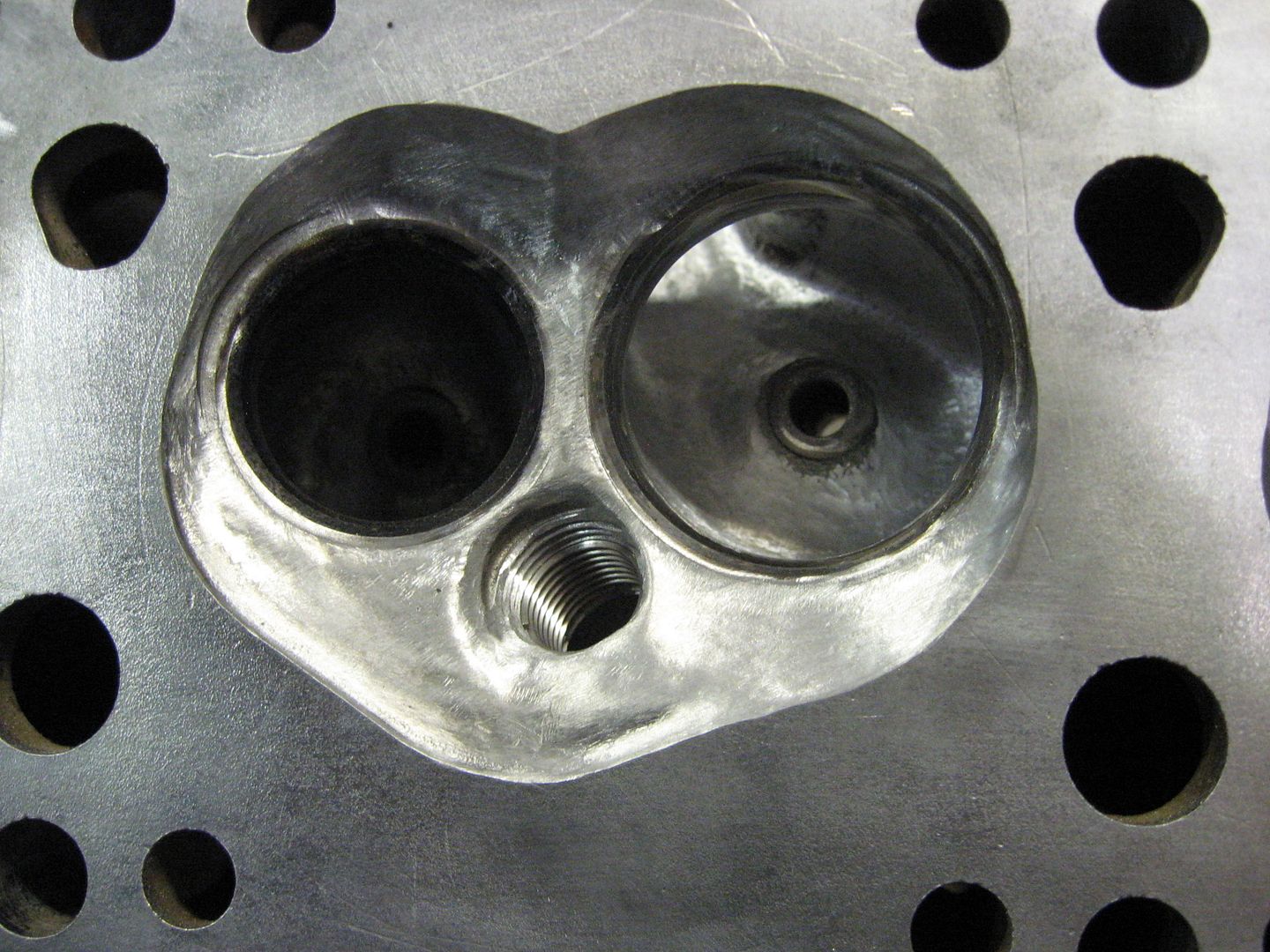
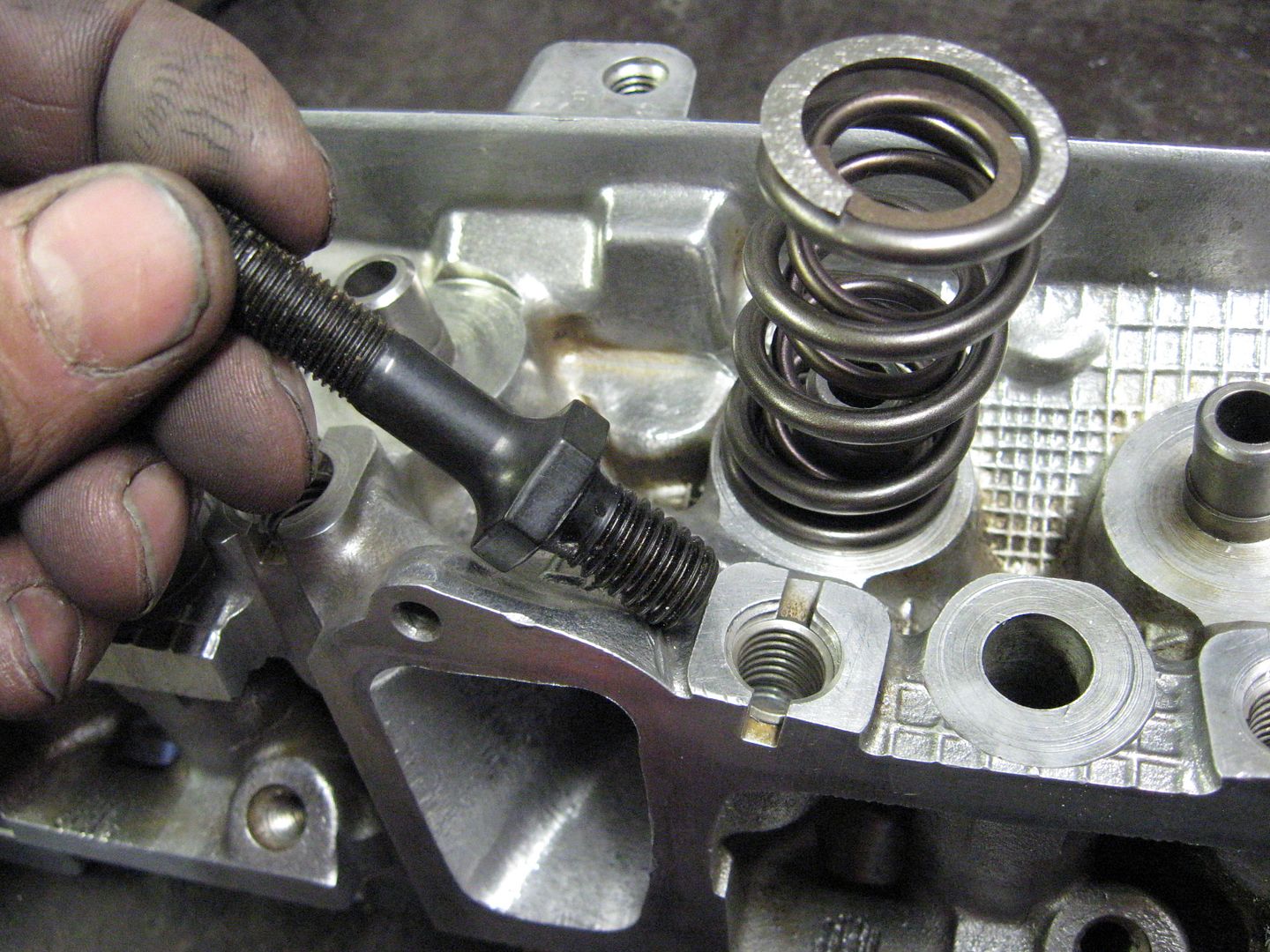
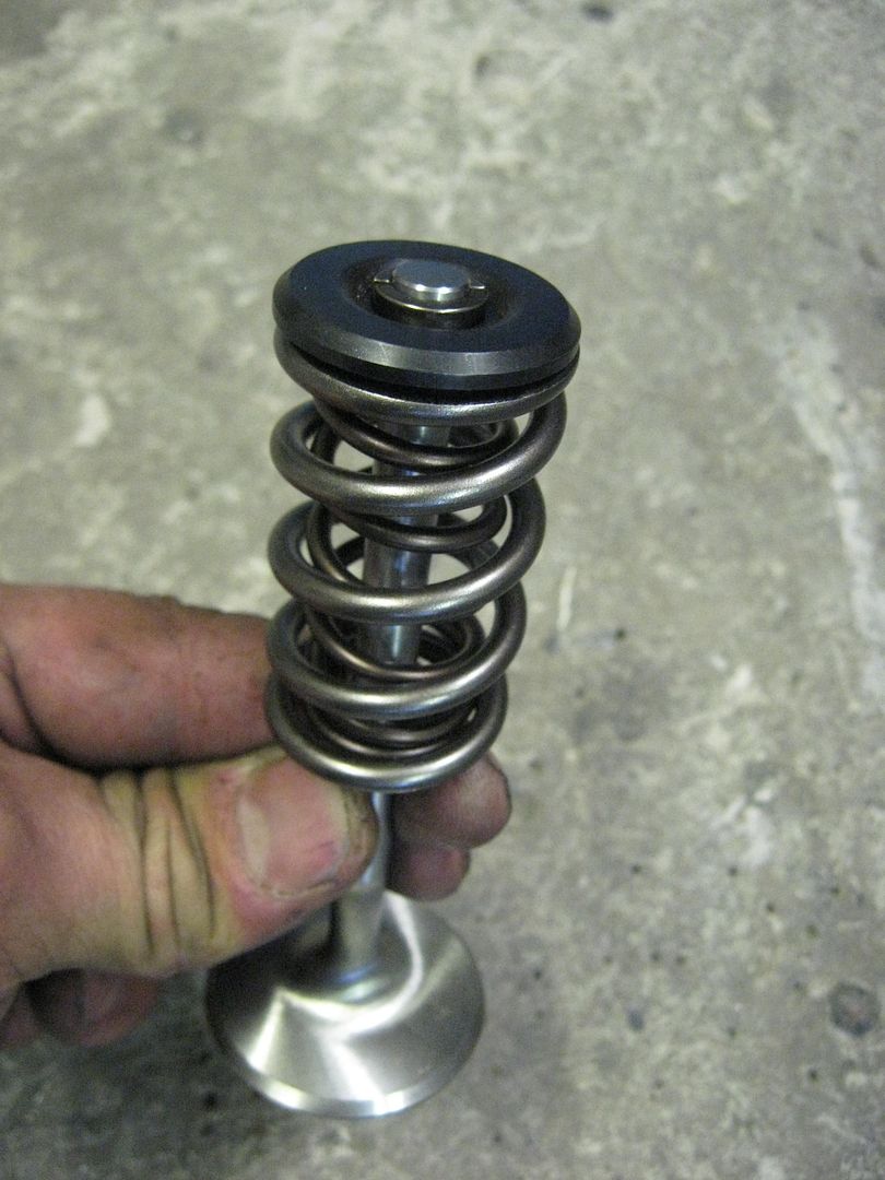
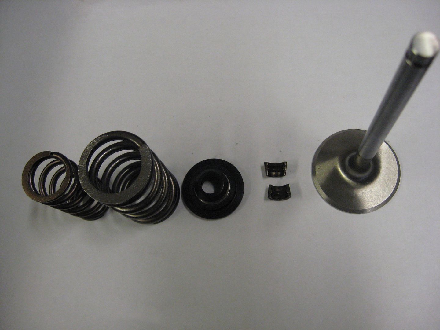
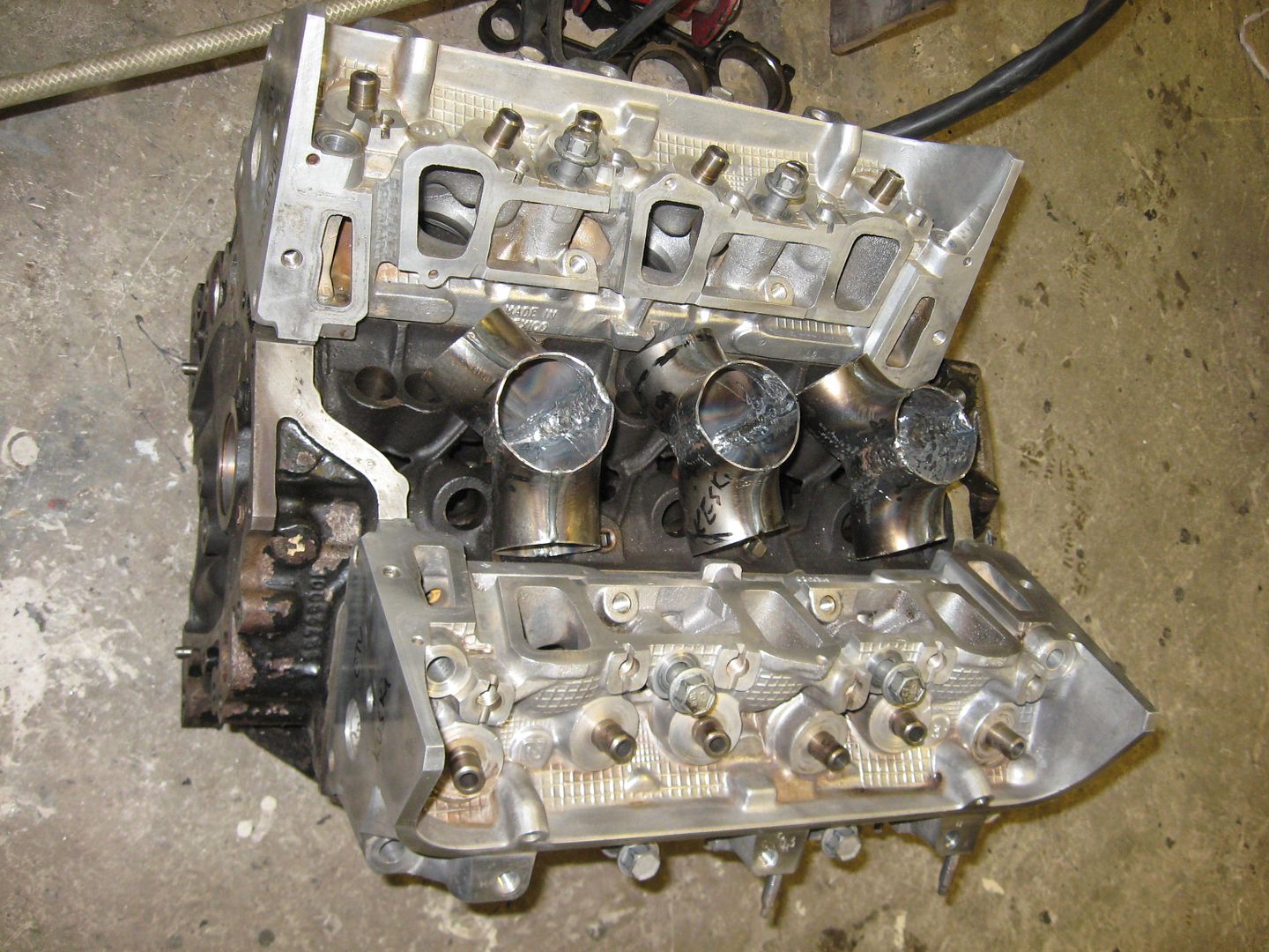
Finally got the 3400 heads back from my friend.
He has been porting them now for half a year.
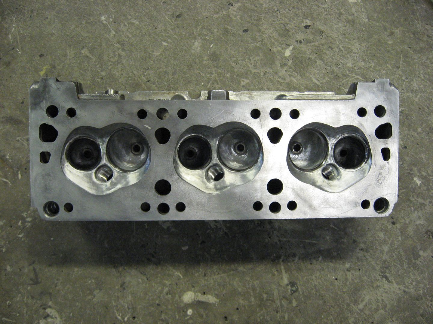
They still need the valve job.
New ARP rocker studs.
Helicoil insert 7/16 " in the head .
Valve springs seat 175 lbs and open 445 lbs.
Valve relief in the pistons.
TDC intake is open 5.14 mm
exhaust is open 3.56 mm
Thats why you need valve reliefs.
Ford Pinto retainers, stock Chevy V6 locks and proudly made in Finland springs.
 Last edited by veekuusi; 05-10-2012, 11:19 AM.
Leave a comment:
-
Got it. It was the lack of a comment that confused me. And the fact that it sounded like the ARP would be too short.Leave a comment:
Leave a comment: