I presume the .58 LPS number is the BSFC for the engine? So the 337 HP is pretty close to what actual is?
Or is the 337 HP based on airflow estimates without efficiency losses taken into account?
-
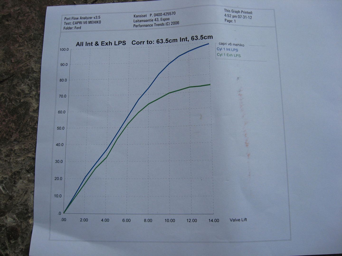
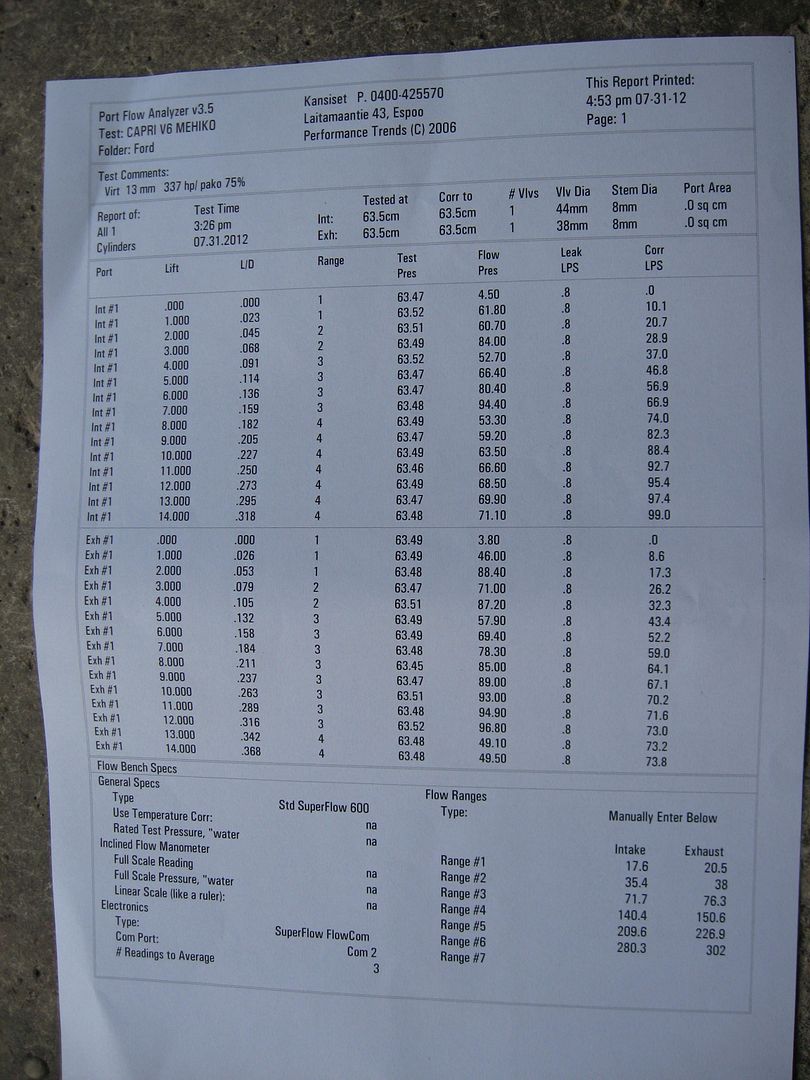
LPS = litres per second
LPS x 2.12 = CFM
So 97 LPS = 206 cfm (13 mm valve lift)
1 LPS = 0.58 horsepower
So 97 x 0.58 x 6 = 337 horsepower (6 cylinder engine)
WOT-TECH has flow numbers something like 236 cfm , .500 valve lift.
I am not going to be doubtful at all.
That is pretty much horsepower from 3400 engine.
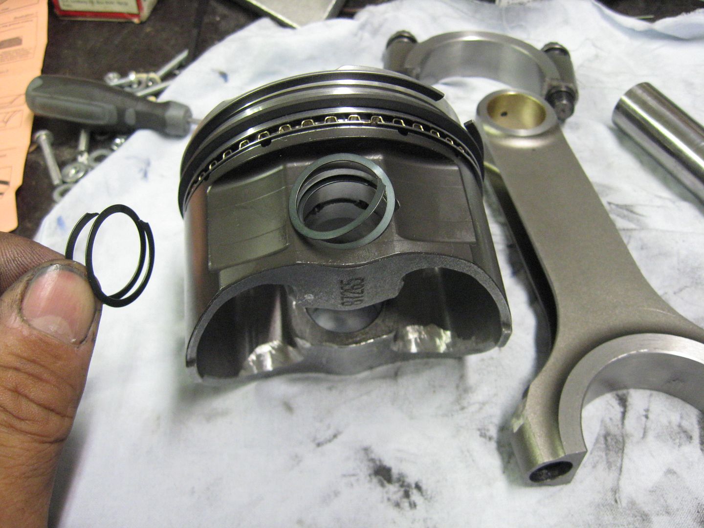
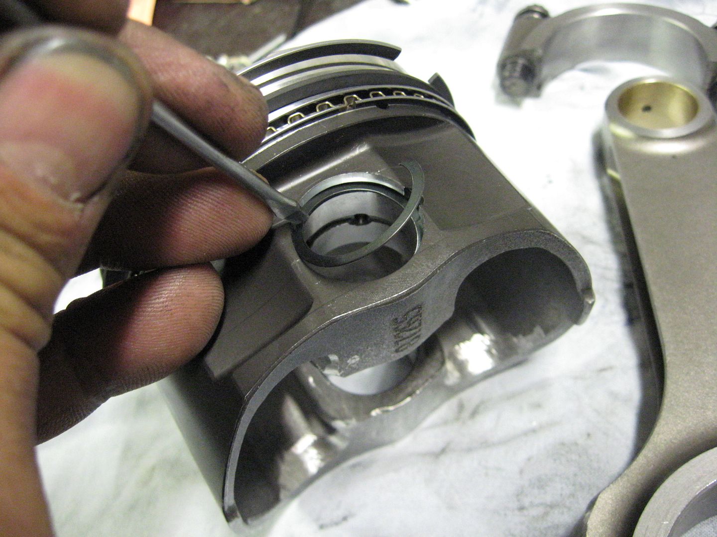
And some engine assembly pictures.
Diamond pistons bore 89.25 mm
Spirolock wrist pin locks
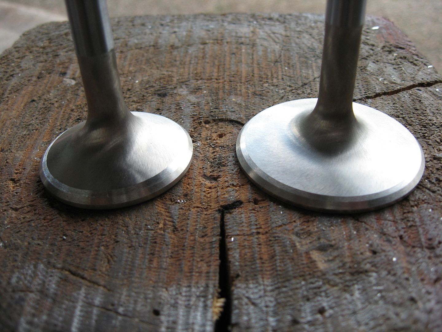
Intake valve full lift 102 degree
 Last edited by veekuusi; 08-06-2012, 12:16 PM.
Leave a comment:
-
I did some rough conversions, looks like .5 lift on the intake side was around 204 cfm. if i get time later on i may try to convert all of it.Leave a comment:
-
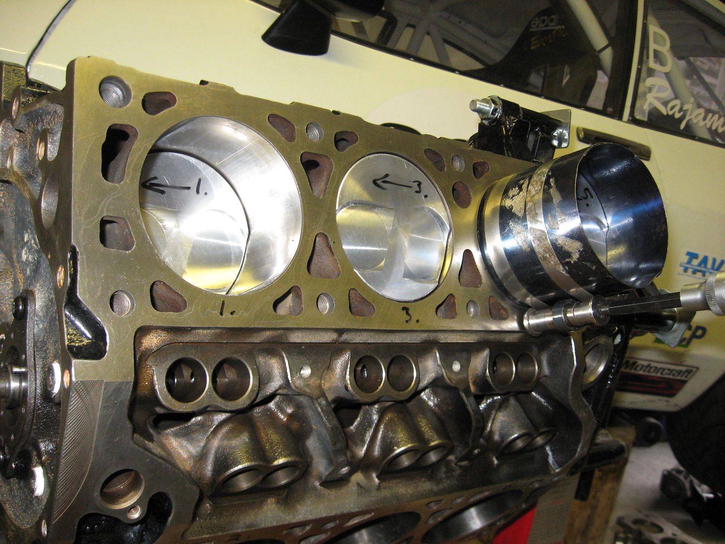
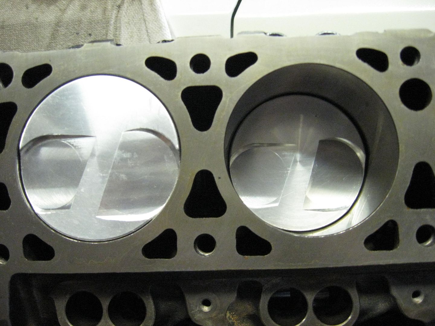
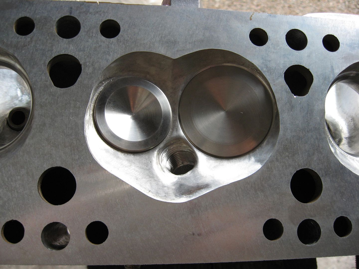
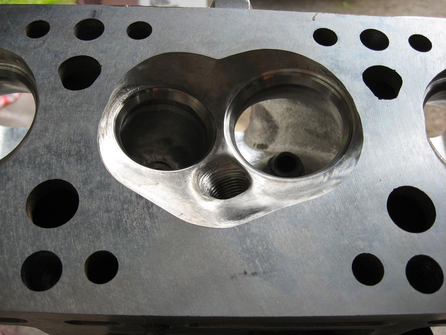
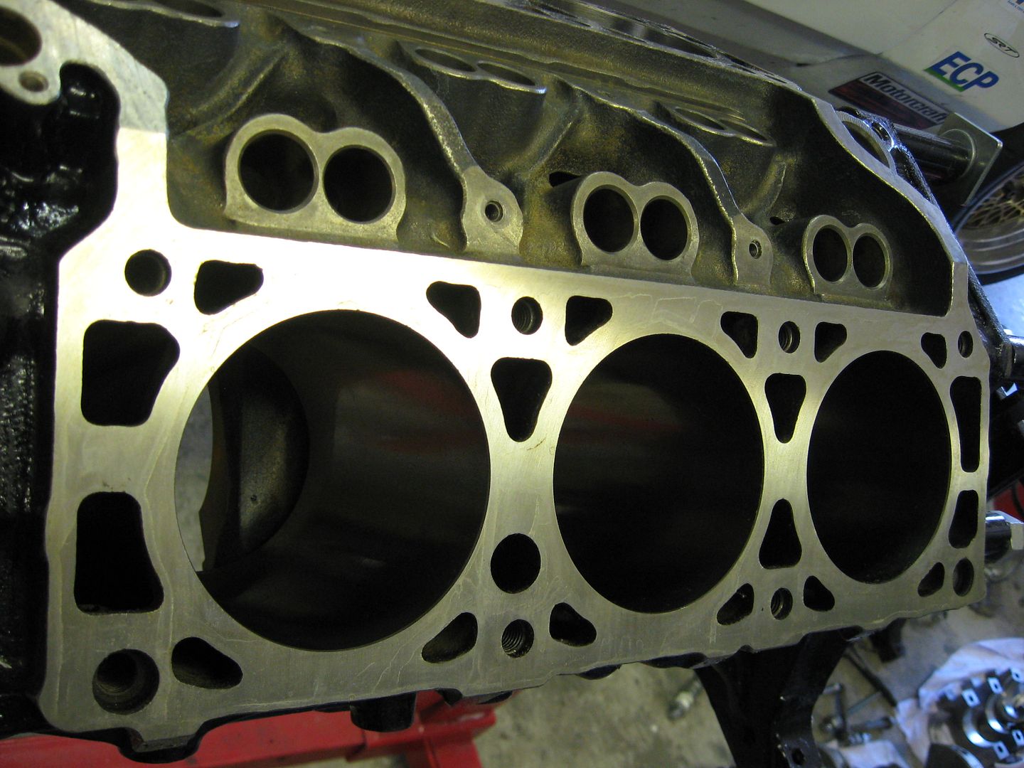
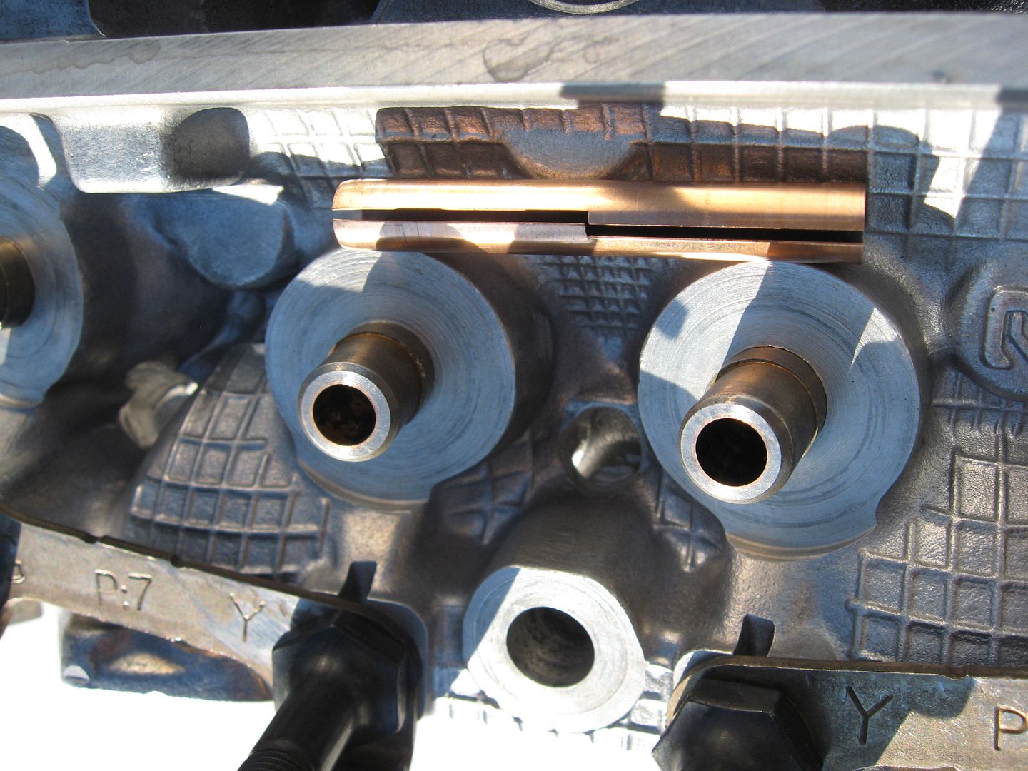
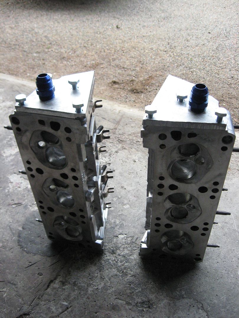
Valve job done.
And some flow bench numbers for DIY 3400 head.
Not bad, 337 horsepower , 13 mm lift (13.2 is max lift in my custom camshaft).
Leave a comment:
-
And finally, the engine assembly can begin.
Just got the block from the shop.
I wanted to mill the block deck surface , so there is no issue with the Cometic head gaskets.
50RA or finer says in the Cometic installation sheet.
"It becomes what it becomes, it is done with a stone".
Said the man in the machine shop, when I asked is he familiar with this installation tip.
He was having a bad day, but the outcome seems to be okay.
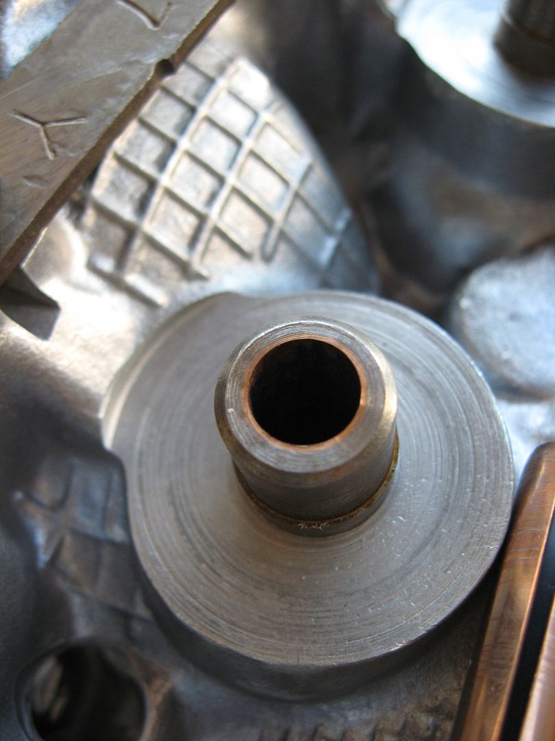
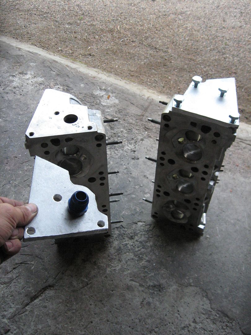
And also the heads were milled, they look quite smooth.
Just to get the scratches away.
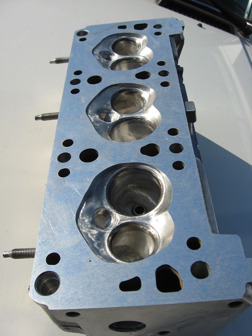
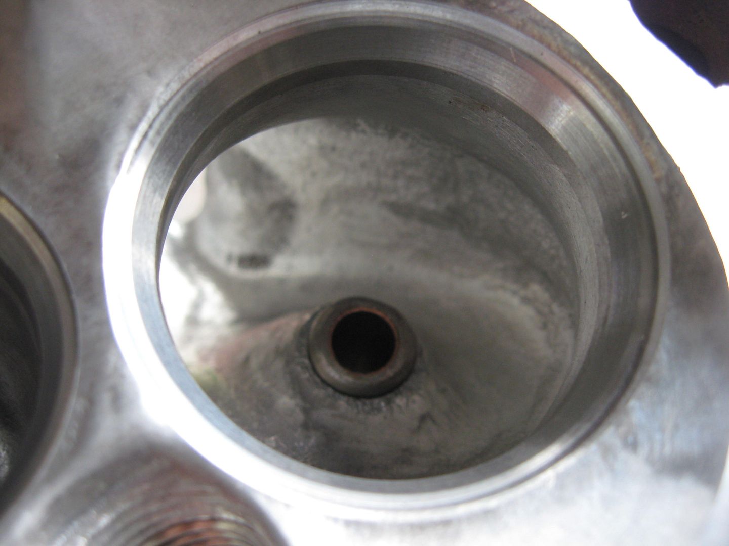
K-line bronze valve guide liners were installed.
KL 1851 C , they have some kind of teflon coating.
"Big boys" adviced me to use them.
 Last edited by veekuusi; 07-28-2012, 01:10 PM.
Leave a comment:
-
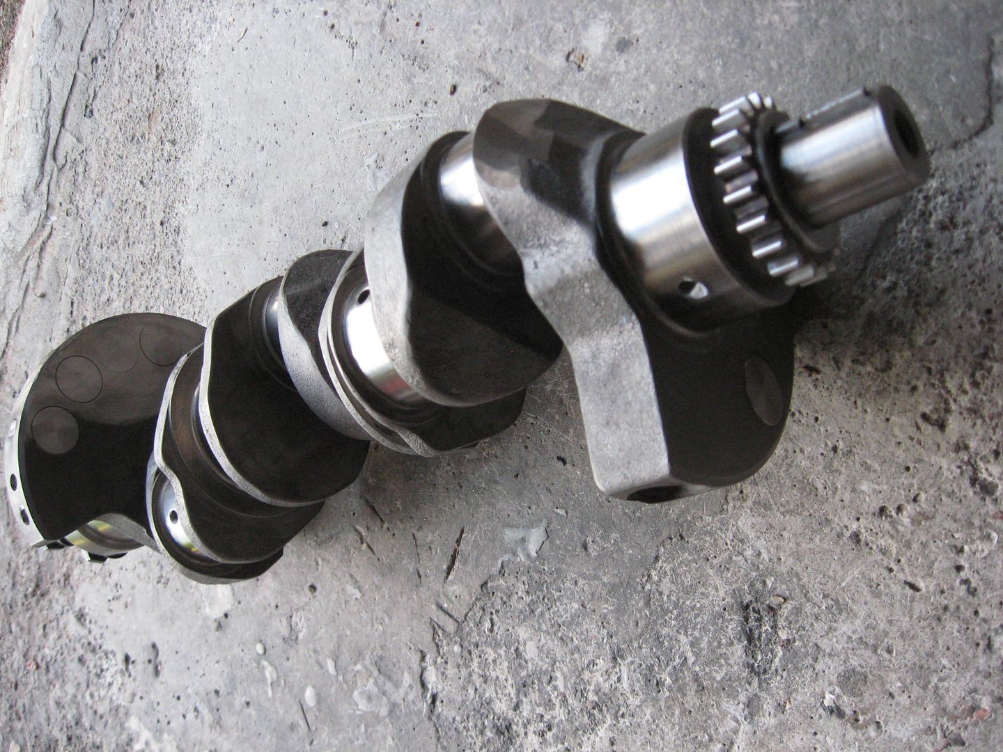
That is a aftermarket crank .
Mains are 67.25 mm (bigger ones).
Manufactured by Eagle (In China, where else).
It is said to take 300 horses which is by the way my goal with this engine.
This crank is maybe the weakest point in my engine.
We will see how much rpm it can take.
And one has to be quite blind , if he does not see the huge play
in the main caps when installing a small bearing crank to a 1996 year block.
At least that engine would not run very far.Last edited by veekuusi; 07-24-2012, 07:51 AM.Leave a comment:
-
That looks like a crank from before 1985 with the smaller main bearings. What is the diameter of the mains? Those early cranks are known to crack.Leave a comment:
-
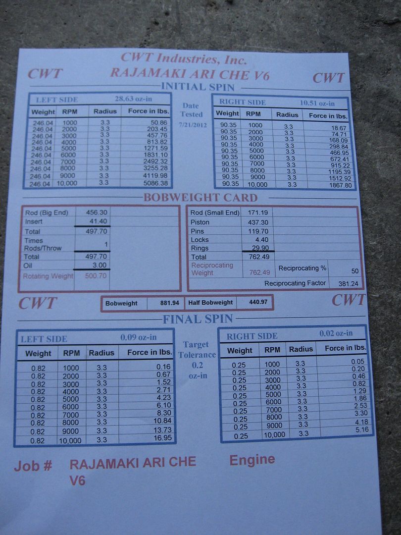
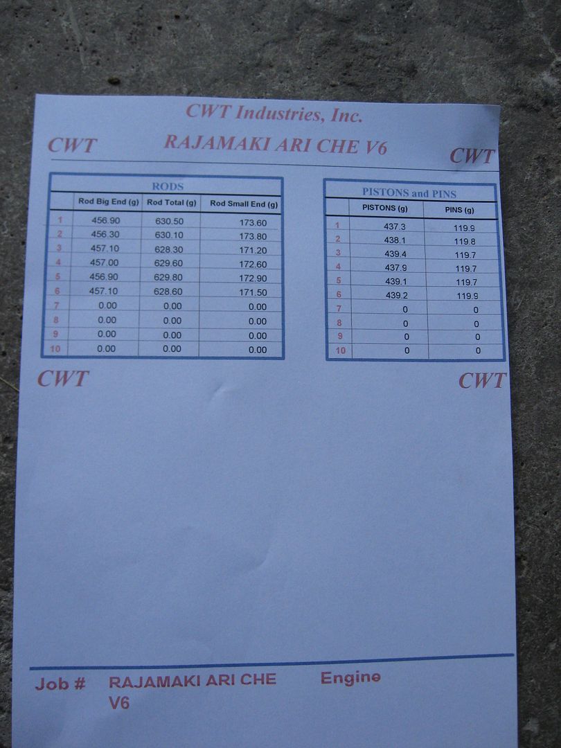
Just got the bottom end back from balancing today.
It was the "second most difficult balancing job" for the machine shop.
Forgot to ask , what was the most difficult.
Five "mallorys" had to be added to the crankshaft.And they did not have enough them,
we had to wait the shipment from USA.
They managed to do it to inner balance.
Although the crankshaft was ment to be outer balanced.
Leave a comment:
-
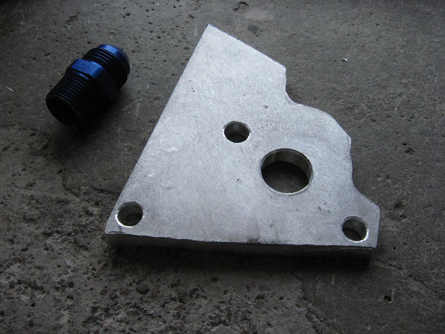
I was going to suggest cutting the tap down as well, ive done that in the past myself
Sent from my iPhone using my iPhone at work cuz I have nothing to doLeave a comment:
-
I was going to suggest grind the tap shorter and if required turn the length of the fitting down.
Also make sure the oil pan is re-gusseted for lateral stiffness.
Might also want to have it re-tempered to a T6 condition. To bring the strength back up.
I'll be doing that if I decide to weld the pan like you did.
Also if you pre-heat the cylinder head to 350-400 F and use a inverter box TIG set at 120-240 HZ you should be able to weld that hole with significant damage to the head.
What engine series is this again? If I have a spare cylinder head I'll get the metallurgy checked on it to verify it is weldable (ie A356 vs a high silica 7000 series alloy).Leave a comment:
-
When working at a machine shop and having a tap bottom out in a hole, we would cut the tap down.Originally posted by veekuusi View PostLeave a comment:


Leave a comment: