Announcement

Collapse
No announcement yet.

Exhaust Collector Discussion

Collapse
X
 
  • Filter
  • Time
  • Show
Clear All
new posts

  • #31
    I agree with the FNG (yeah you Jon, lol). You don't need to get so elaborate with turbo collectors beyond a nice merge. In N/A applications it is more important, but making collectors like the ones below are difficult enough to make, nevermind "vortex collectors"...
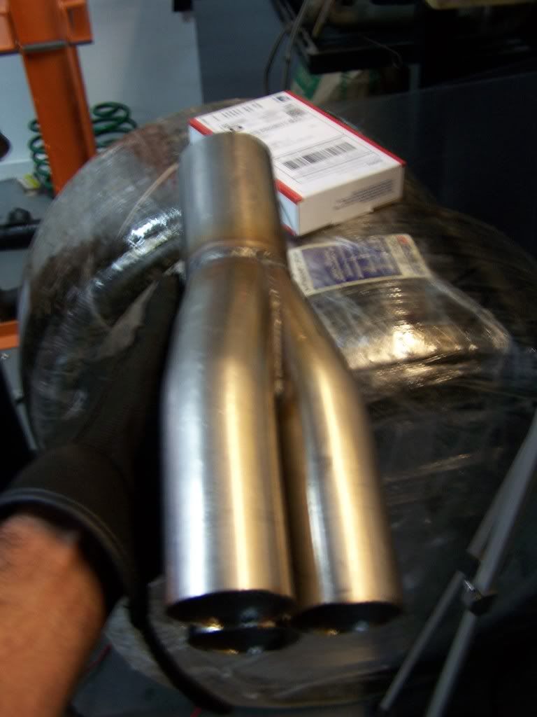
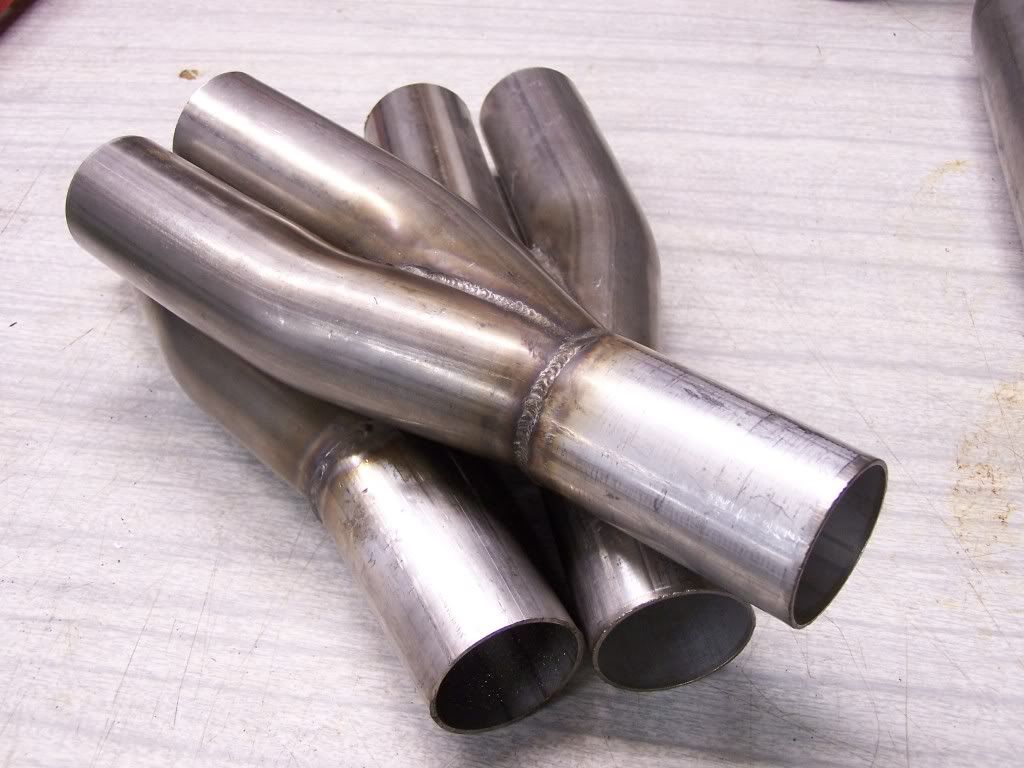


    I don't like using thin walled pipe for turbo applications, they always crack unless you have extreme turbo bracing since the heat cycles will practically melt - used 14ga on a couple applications and they held with extra welding and bracing, but the sch10 will hold the weight, heat and is actually easier to weld.

    I also used that Honda forum to get ideas to make a jig to produce the above collectors, but had to change things a bit since I was using 18degree bends for a Burns-style collector rather than sch10 straight piping. The 2-1's were made on the bandsaw, the 3-1 was made on a metal cutoff saw.

    I will disagree, though, that collector design doesn't matter. In N/A, S/C and nitrous applications, it is VERY important. A local here with an outlaw Buick Regal (7second car) picked up several tenths by switching to a Burns collector and larger primaries.
    Links:
    WOT-Tech.com
    FaceBook
    Instagram

    Comment


    • #32
      I decided to try a different, less intensive approach. And it just so happened to be just like the pics ForcedFirebird posted.

      And it will be easier to pipe together since the 3 inlets are lined up side by side.

      Click image for larger version

Name:	v6 collector reverse merge.jpg
Views:	1
Size:	103.0 KB
ID:	376813

      My theory, atm, is to take a tried and true method described above. Then attempt to achieve perfection in measurements, cuts, blending, polishing, etc.

      The nice part about this style is the ease of cutting. It is a straight line cut from above.


      I heard once the header is ineffective with turbochargers. Is this true? It seems the impulse from the opening valve should still create a reversion wave at the collector regardless if there is a turbine down stream or not. Unless I am wrong....
      Last edited by TGP37; 08-16-2011, 05:08 PM.
      1996 Grand Prix | 3100v6 L82 | T04E-50 Turbo | Getrag 282 w/ EP LSD | SPEC-3 Clutch

      Comment


      • #33
        Originally posted by TGP37 View Post
        I decided to try a different, less intensive approach. And it just so happened to be just like the pics ForcedFirebird posted.

        And it will be easier to pipe together since the 3 inlets are lined up side by side.

        [ATTACH=CONFIG]6056[/ATTACH]

        My theory, atm, is to take a tried and true method described above. Then attempt to achieve perfection in measurements, cuts, blending, polishing, etc.

        The nice part about this style is the ease of cutting. It is a straight line cut from above.


        I heard once the header is ineffective with turbochargers. Is this true? It seems the impulse from the opening valve should still create a reversion wave at the collector regardless if there is a turbine down stream or not. Unless I am wrong....
        why are you knecking down the collector then bringing it back to a full sized pipe diameter? At least it looks that way. I know on NA applications this is done to produce an effect, but on a turbo app this will actually hurt gas velocity as it enters the turbo. you want to come out of the collectors into either smaller piping or same size piping as the outlet at the collector. enlarging it i would think would have a negative effect on velocity.

        Comment


        • #34
          Originally posted by ForcedFirebird View Post
          I agree with the FNG (yeah you Jon, lol). You don't need to get so elaborate with turbo collectors beyond a nice merge. In N/A applications it is more important, but making collectors like the ones below are difficult enough to make, nevermind "vortex collectors"...


          I don't like using thin walled pipe for turbo applications, they always crack unless you have extreme turbo bracing since the heat cycles will practically melt - used 14ga on a couple applications and they held with extra welding and bracing, but the sch10 will hold the weight, heat and is actually easier to weld.

          I also used that Honda forum to get ideas to make a jig to produce the above collectors, but had to change things a bit since I was using 18degree bends for a Burns-style collector rather than sch10 straight piping. The 2-1's were made on the bandsaw, the 3-1 was made on a metal cutoff saw.

          I will disagree, though, that collector design doesn't matter. In N/A, S/C and nitrous applications, it is VERY important. A local here with an outlaw Buick Regal (7second car) picked up several tenths by switching to a Burns collector and larger primaries.
          i completely agree in NA sc and nitrous apps that collector design is important. the reason is because you are using the exhaust gases in a different means. in a SC i would think its a little less important as bigger is probably better just to get the pressure out faster. NA and nitrous you are working with uncompressed intake charges and you are using the motor to move the air and the exhaust system as part of the "pump" to keep it moving. i have read up on the theory, but it is in one ear out the other because i refuse to spend time building NA setups when for the same amount of money we can normally double the output with a simple forced induction setup.

          Comment


          • #35
            Originally posted by slw240sx View Post
            NA and nitrous you are working with uncompressed intake charges and you are using the motor to move the air and the exhaust system as part of the "pump" to keep it moving. i have read up on the theory, but it is in one ear out the other because i refuse to spend time building NA setups when for the same amount of money we can normally double the output with a simple forced induction setup.
            It's called scavenging. Drawing the exhaust out faster than it would normally flow out to help evacuate the cylinder, sort of like removing the EGR. It also somewhat produces a vacuum when valve overlap occurs.

            Here's what wiki says about it:

            Originally posted by Wiki
            When an engine starts its exhaust stroke, the piston moves up the cylinder bore, decreasing the total chamber volume. When the exhaust valve opens, the high pressure exhaust gas escapes into the exhaust manifold or header, creating an exhaust pulse comprising three main parts: The high-pressure head is created by the large pressure difference between the exhaust in the combustion chamber and the atmospheric pressure outside of the exhaust system. As the exhaust gases equalize between the combustion chamber and the atmosphere, the difference in pressure decreases and the exhaust velocity decreases. This forms the medium-pressure body component of the exhaust pulse. The remaining exhaust gas forms the low-pressure tail component. This tail component may initially match ambient atmospheric pressure, but the momentum of the high- and medium- pressure components reduces the pressure in the combustion chamber to a lower-than-atmospheric level. This relatively low pressure helps to extract all the combustion products from the cylinder and induct the intake charge during the overlap period when both intake and exhaust valves are partially open. The effect is known as scavenging. Length, cross-sectional area, and shaping of the exhaust ports and pipeworks influences the degree of scavenging effect, and the engine speed range over which scavenging occurs.

            The magnitude of the exhaust scavenging effect is a direct function of the velocity of the high and medium pressure components of the exhaust pulse. Performance headers work to increase the exhaust velocity as much as possible. One technique is tuned-length primary tubes. This technique attempts to time the occurrence of each exhaust pulse, to occur one after the other in succession while still in the exhaust system. The lower pressure tail of an exhaust pulse then serves to create a greater pressure difference between the high pressure head of the next exhaust pulse, thus increasing the velocity of that exhaust pulse. In V6 and V8 engines where there is more than one exhaust bank, Y-pipes and X-pipes work on the same principle of using the low pressure component of an exhaust pulse to increase the velocity of the next exhaust pulse.

            Great care must be used when selecting the length and diameter of the primary tubes. Tubes that are too large will cause the exhaust gas to expand and slow down, decreasing the scavenging effect. Tubes that are too small will create exhaust flow resistance which the engine must work to expel the exhaust gas from the chamber, reducing power and leaving exhaust in the chamber to dilute the incoming intake charge. Since engines produce more exhaust gas at higher speeds, the header(s) are tuned to a particular engine speed range according to the intended application. Typically, wide primary tubes offer the best gains in power and torque at higher engine speeds, while narrow tubes offer the best gains at lower speeds.

            Many headers are also resonance tuned, to utilize the low-pressure reflected wave rarefaction pulse which can help scavenging the combustion chamber during valve overlap. This pulse is created in all exhaust systems each time a change in density occurs, such as when exhaust merges into the collector. For clarification, the rarefaction pulse is the technical term for the same process that was described above in the "head, body, tail" description. By tuning the length of the primary tubes, usually by means of resonance tuning, the rarefaction pulse can be timed to coincide with the exact moment valve overlap occurs. Typically, long primary tubes resonate at a lower engine speed than short primary tubes.


            Header designs on NA builds are very important.
            -60v6's 2nd Jon M.
            91 Black Lumina Z34-5 speed
            92 Black Lumina Z34 5 speed (getting there, slowly... follow the progress here)
            94 Red Ford Ranger 2WD-5 speed
            Originally posted by Jay Leno
            Tires are cheap clutches...

            Comment


            • #36
              Originally posted by slw240sx View Post
              why are you knecking down the collector then bringing it back to a full sized pipe diameter? At least it looks that way. I know on NA applications this is done to produce an effect, but on a turbo app this will actually hurt gas velocity as it enters the turbo. you want to come out of the collectors into either smaller piping or same size piping as the outlet at the collector. enlarging it i would think would have a negative effect on velocity.
              Thank you, this is exactly why I post here. I have a lot to learn yet, but I am on my way.

              I am taking your advise and removing the taper. I thought it was for velocity but didn't realize the difference in turbo apps. Speaking of the collector, I still yet have to find the idea diameter for the primaries. Also need to figure the cross-sectional ratio from 3 smaller pipes to one larger pipe. Should I maintain equal cross section area?

              Example,

              Using 16 gauge as the example (roughly 0.0625" or 1/16" thick)
              Primaries, 1.75" OD / 1.7375" ID
              Surface Area of Circle = 2.37"²
              Three Primaries Total = 7.11"²

              Secondary Pipe Diameter = 3" (which is A= 7.11"²)

              But if I go 1.5" Primaries then the secondary should be (1.767"² * 3 = 5.3"²) diameter of 2.6" ID , 2.725" OD.

              But it seems excessive to have two 3" pipes merging into the Turbo. But that is how the math states it.

              Any advise there?

              EDIT UPDATE: I think I am missing pressure as a factor and that all 3 exhaust primaries aren't flowing at once. So I think I should approach the equation with mass instead of volume. And then knowing the average ambient pressure in the header primary while valve closed and when there is flow. So then the secondary pipe should flow (2x ambient PSI + 1x boosted exhaust PSI ) = secondary diameter to maintain steady velocity for a given PSI during 1 primary flowing. Ugh, thats gonna be a cruncher. I need to read up on my physics books I have lying around.

              Originally posted by pocket-rocket View Post
              It's called scavenging. Drawing the exhaust out faster than it would normally flow out to help evacuate the cylinder, sort of like removing the EGR. It also somewhat produces a vacuum when valve overlap occurs.

              Header designs on NA builds are very important.
              Here is the big question, Why do people say the header won't work the same on a turbo?

              I know it seems like a silly question but if the scavenging effect is created at the collector, then in theory exhaust under pressure would still create a lesser pressure reversion wave which would aid the excavation of exhaust gases under greater pressures and heat. Same mechanics just at a higher pressure with greater heat. But what of the turbines effect on all of that?
              Last edited by TGP37; 08-16-2011, 10:08 PM.
              1996 Grand Prix | 3100v6 L82 | T04E-50 Turbo | Getrag 282 w/ EP LSD | SPEC-3 Clutch

              Comment


              • #37
                Originally posted by TGP37 View Post
                Thank you, this is exactly why I post here. I have a lot to learn yet, but I am on my way.

                I am taking your advise and removing the taper. I thought it was for velocity but didn't realize the difference in turbo apps. Speaking of the collector, I still yet have to find the idea diameter for the primaries. Also need to figure the cross-sectional ratio from 3 smaller pipes to one larger pipe. Should I maintain equal cross section area?

                Example,

                Using 16 gauge as the example (roughly 0.0625" or 1/16" thick)
                Primaries, 1.75" OD / 1.7375" ID
                Surface Area of Circle = 2.37"²
                Three Primaries Total = 7.11"²

                Secondary Pipe Diameter = 3" (which is A= 7.11"²)

                But if I go 1.5" Primaries then the secondary should be (1.767"² * 3 = 5.3"²) diameter of 2.6" ID , 2.725" OD.

                But it seems excessive to have two 3" pipes merging into the Turbo. But that is how the math states it.

                Any advise there?


                Here is the big question, Why do people say the header won't work the same on a turbo?

                I know it seems like a silly question but if the scavenging effect is created at the collector, then in theory exhaust under pressure would still create a lesser pressure reversion wave which would aid the excavation of exhaust gases under greater pressures and heat. Same mechanics just at a higher pressure with greater heat. But what of the turbines effect on all of that?
                ideal primary size honestly will just match port size. we use 1-5/8ths primary runners, they fit the port size and inside the flanges we had designed. smaller will work on lower boost setups, i am not against 1.5" primary runners. We used 1.5" on our turbo mustang kits for the most part and those guys where consistently pushing 550whp. of course a ford 302 has silly small exhaust ports.
                honestly you could build your kit using 1.5" runners and 2" crossover pipes and make as much power as you want. we use 1-5/8ths and 2.5" crossover pipes, the reason is that with our pressed collectors that is the outlet size of the collector. There is no need for 3" pipe going into the turbo. The inlet of the turbo is about 2.5" in diameter just rectangled. you would have a hard time getting 3" to fit a t3 flange. t4 flanges we use 3" into the turbo, but we still would use a 2.5" crossover merging to a 3" section to fit the turbo.

                I rarely to the math on this stuff anymore. to be honest back in the day we did concern ourselves with the math behind tube size and all that, but over the years we have just found that you lose about an hour or two of labor arguing the engineering behind the parts instead of getting busy and just building something that in the real world normally works. Ill be honest i am a high school drop out that failed bad in math, i prefer to just build and test out what i think in my head make sense. most of the time i am right. after building hundreds of setups you kind of just get the feel for what will be enough and what will be over kill. luckily i have had some very good engineer students work for me over the years as well as a few good math people that also were HS dropouts that tend to be like you who want to do the math. i but heads with them and do real world testing while they punch numbers, we usually come out in compromise of whats perfect in theory and what works in the real world.

                here are some links to my work on our photobucket and flickr pages this is all work over the last few years, most is undocumented unfortunately.
                http://s253.photobucket.com/albums/hh75/ForcedFabllc/
                http://www.flickr.com/photos/forcedfab/sets/
                Last edited by slw240sx; 08-16-2011, 09:47 PM.

                Comment


                • #38
                  Originally posted by slw240sx View Post
                  ideal primary size honestly will just match port size.
                  You can make something work, but you aren't making it ideal.

                  Originally posted by slw240sx View Post
                  1.5" runners and 2" crossover pipes and make as much power as you want. we use 1-5/8ths and 2.5" crossover pipes, the reason is that with our pressed collectors that is the outlet size of the collector.
                  Good reason to use those sizes, if you are more concerned with making something work without any regard to how good you could have made it. Pretty sure we are trying to figure out the best way to go about it, not the best way to make it happen easily.
                  Ben
                  60DegreeV6.com
                  WOT-Tech.com

                  Comment


                  • #39
                    Originally posted by SappySE107 View Post
                    You can make something work, but you aren't making it ideal.


                    Good reason to use those sizes, if you are more concerned with making something work without any regard to how good you could have made it. Pretty sure we are trying to figure out the best way to go about it, not the best way to make it happen easily.
                    Precisely, I am interested in making a real life working exhaust system built to very specific dimensions to achieve a state of greater function/efficiency.

                    And here is a question I just thought of.....

                    Would it be ideal to maintain a steady velocity all the way to the tips? In such a case, the pipes would need a very gradual taper equal to the volume lost from temp transfer (which can be test measured). Or would it be better to have curves that are a little larger in diameter (2" straight with 2.25" mandrel) so the gases slow down and take the turn easier? Like the intake does.

                    Now, I know having perfectly even taper is a little far fetched. But knowing certain data we could choose what diameter is needed down the way. I'm sure there might be more to plan instead of just running a diameter pipe from the really hot turbo out to the cool muffler inlet.

                    It would be interesting to have an exhaust that maintained a very steady velocity under wot.
                    Last edited by TGP37; 08-16-2011, 10:21 PM.
                    1996 Grand Prix | 3100v6 L82 | T04E-50 Turbo | Getrag 282 w/ EP LSD | SPEC-3 Clutch

                    Comment


                    • #40
                      Originally posted by TGP37 View Post
                      Precisely, I am interested in making a real life working exhaust system built to very specific dimensions to achieve a state of greater function/efficiency.

                      And here is a question I just thought of.....

                      Would it be ideal to maintain a steady velocity all the way to the tips? In such a case, the pipes would need a very gradual taper equal to the volume lost from temp transfer (which can be test measured). Or would it be better to have curves that are a little larger in diameter (2" straight with 2.25" mandrel) so the gases slow down and take the turn easier? Like the intake does.

                      Now, I know having perfectly even taper is a little far fetched. But knowing certain data we could choose what diameter is needed down the way. I'm sure there might be more to plan instead of just running a diameter pipe from the really hot turbo out to the cool muffler inlet.

                      It would be interesting to have an exhaust that maintained a very steady velocity under wot.
                      once again, i wont even argue with you guys. you are over complicating this. im guessing you enjoy the math behind these things more then the driving part of the project?

                      a turbo wants no restriction after the turbine. it needs no back pressure it needs to be as open and free flowing as possible.

                      Comment


                      • #41
                        Originally posted by slw240sx View Post
                        once again, i wont even argue with you guys. you are over complicating this. im guessing you enjoy the math behind these things more then the driving part of the project?

                        a turbo wants no restriction after the turbine. it needs no back pressure it needs to be as open and free flowing as possible.
                        Is NASCAR or other professional drag teams over complicating their creations? Imagine all the hours, test, products just to squeeze that extra 1 HP. There is a science to this, we both know this. And I am only 2 years experienced so far with this stuff. So please stop telling me to "dumb" it down, I won't. I am going to build these collectors regardless.

                        I don't see anything wrong dedicating time to design a great pair of turbo headers. Every little bit counts, which is why mandrel bends are popular. Who knows, maybe I stumble upon something great.

                        I wish you were more productive towards the discussion instead of having this "Silence all who questions the normal methods" attitude.
                        1996 Grand Prix | 3100v6 L82 | T04E-50 Turbo | Getrag 282 w/ EP LSD | SPEC-3 Clutch

                        Comment


                        • #42
                          Originally posted by slw240sx View Post
                          you are over complicating this. im guessing you enjoy the math behind these things more then the driving part of the project?
                          Doing the former makes the latter better.
                          Ben
                          60DegreeV6.com
                          WOT-Tech.com

                          Comment


                          • #43
                            Originally posted by TGP37 View Post
                            Is NASCAR or other professional drag teams over complicating their creations? Imagine all the hours, test, products just to squeeze that extra 1 HP. There is a science to this, we both know this. And I am only 2 years experienced so far with this stuff. So please stop telling me to "dumb" it down, I won't. I am going to build these collectors regardless.

                            I don't see anything wrong dedicating time to design a great pair of turbo headers. Every little bit counts, which is why mandrel bends are popular. Who knows, maybe I stumble upon something great.

                            I wish you were more productive towards the discussion instead of having this "Silence all who questions the normal methods" attitude.

                            thats a silly comparison. that is professional top teir racing. you and i are not top tier multimillion dollar research dept's. your time dedicated into a great pair of turbo headers go completely in vain when the execution is not going to compliment the time spent working the numbers. every little bit helps. i think you guys give way to much credit to that little stuff. end results are end results building this all in perfection on paper is more then likely not going to be the same in reality when you have to work around the engine bay and all the constraints of the car. then you have the actual kit that will change variables. every joint you make thats slightly misaligned, every flex section you include, the slightly off radius cuts that wont quite match up, every little one of those inconsistencies changes that math.

                            i argue against this sort of over complication because i see a different way to build a car then the engineers that want theoretical correctness. i look at building a car in simple terms. what is the purpose for the car? drag racing, street machine, road race, or drift car. Then i look at what type of power band we want to shoot for. great low torque, nice flat curve, or peaky power. different types of racing you have to adjust to them. then we set a power goal 250hp, 500hp 800hp like that. that is what is truly important to a customer that is building a car. If i started spouting off theories and math formulas 99% of them would look at me and just tell me they want to go fast or slide around in third gear. They do not care how its done. at the end of the day if you build kit A and i build Kit B we are both going to come out very similar. i know where my time and attention went. That is into the parts the build quality and aesthetics. knowing already that my setup will be capable of a power goal i set. do i need to stress over calculations to figure out if my goal is what ill hit? no. I know from hands on experience what is needed to attain the goal. I do not like math enough to enjoy what engineers do. i would never be a engineer. i would always end up the fabricator building from the drawings of the engineer.

                            there is nothing wrong with dedicating your time to a great pair of headers. Id just dont like to see people spending countless hours trying to reinvent the wheel. there are build formulas in every community to follow and most are built upon years of trial and error from people like you, and people like myself working to achieve the same end result. You keep doing what you are doing, and ill keep doing what i am doing. honestly your the type of person i rely on to give a me a base for real world trial and error when building a product, so you role is important even if i give you a hard time for over complicating it. In new development i may come back and read through your ideas on theory and may try to apply them. i have gathered so much information from so many different places that you never know a discussion you had 5 years ago may hold some key info to something you work on tomorrow.

                            Comment


                            • #44
                              Originally posted by SappySE107 View Post
                              Doing the former makes the latter better.
                              in my years of experience people who are this way are more likely to abandon a project before its ever even road worthy.


                              Also if i may, for being a leading figure in this community you awfully hostile to people who are engaged in a friendly discussion. I know we are on different sides of the discussion, but if you are going to involve yourself at least take the hostility down a few notches and try to at least engage me into being open minded. I think you have the wrong idea of my intentions or demeanor. I know i am a total asshole and i am stubborn, but i am also very reasonable and do try to be respectful. dislike my posts with me dumbing down and what not i get that, but be respectful and try to be constructive. That is what makes me not like your posts. they are more often then not attempts at cheap zings rather then a good counter point. Your partner joined in the convo and i actually expected hostility from him as well, but he was welcoming and brought up a good point.

                              Comment


                              • #45
                                Originally posted by slw240sx View Post
                                in my years of experience people who are this way are more likely to abandon a project before its ever even road worthy.


                                Also if i may, for being a leading figure in this community you awfully hostile to people who are engaged in a friendly discussion. I know we are on different sides of the discussion, but if you are going to involve yourself at least take the hostility down a few notches and try to at least engage me into being open minded. I think you have the wrong idea of my intentions or demeanor. I know i am a total asshole and i am stubborn, but i am also very reasonable and do try to be respectful. dislike my posts with me dumbing down and what not i get that, but be respectful and try to be constructive. That is what makes me not like your posts. they are more often then not attempts at cheap zings rather then a good counter point. Your partner joined in the convo and i actually expected hostility from him as well, but he was welcoming and brought up a good point.
                                If my fab guy joined a competitors website/forum and told them he didn't care about doing the best he could...id fire him. Instantly.
                                Ben
                                60DegreeV6.com
                                WOT-Tech.com

                                Comment

                                Working...
                                X