Announcement

Collapse
No announcement yet.

Porting suggestions/pics for 3x00 heads

Collapse
X
 
  • Filter
  • Time
  • Show
Clear All
new posts

  • #16
    Oh it never ends really. I want to setup a wet flowbench later (because fuel injection doesn't mean the mixture is moot... far from it). That would be the best way to go, but even then you are looking at a lot of time to test with different pressures, to make it even more valid. Since engines don't flow at a steady depression, you would have to do a lot of tests based on RPM and simulation data.

    The 3500 has a lot of advantages but I am not sure the ultimate 3400 or 3500 based boost build will use 3500 heads.
    Ben
    60DegreeV6.com
    WOT-Tech.com

    Comment


    • #17
      Originally posted by SappySE107 View Post

      The 3500 has a lot of advantages but I am not sure the ultimate 3400 or 3500 based boost build will use 3500 heads.
      Yes, I know. We have discussed this earlier. You said because of the lack of aftermarket parts on the 3500, the 3400 boost-ported heads could be better. The deal I got for the 3500 top end was hard to pass up, along with the advantage of using the 3.4 Camaro pistons during the N/A tuning and testing with the larger chambers was enticing.

      Is there a difference when flowing on the bench to simulate boost vs N/A? I was pondering today, and thought "Is there a difference where the static pressure is?".

      Or, if the valve is seeing vacuum on one side during an N/A test, does it make a difference if it sees boost on the other side during the test with all other variables equal, or is flow just flow?

      With the machines I now have available to me, perhaps I'm getting way too anal?
      Last edited by ForcedFirebird; 09-21-2007, 11:07 PM.
      Links:
      WOT-Tech.com
      FaceBook
      Instagram

      Comment


      • #18
        Yes, it will matter but you are looking at different pressure with boost just like NA. You can make testing as complicated as you want really:P Its all still depression in cylinder and it still flows both directions based on rpm and cam timing. You would just change the depression on the flowbench but to know what depression to really test at for closer to real world would take some fancy equipment indeed.

        3500 top end will still produce a lot more power than most ported 3400 heads so no worries there on your decision
        Ben
        60DegreeV6.com
        WOT-Tech.com

        Comment


        • #19
          Speaking of fancy equipment, I was looking around a benches/accy's after you mentioned it. There is a valve-spring opening tool that can mounted to your bench to mimick these "real life" scenarios. Thought that was interesting, and wondered if you could "program" cam timing into them to help further the understanding of flow in real-world applications.


          Did you build your bench from a design/plans? I found the flow quik components you mentioned, but couldn't find any kind of dimensions/drawings to use to build one. There was diagrams of some commercial units, though. I also saw where people are using two vacuums with a "y" fitting to up the cfm capabilities.
          Links:
          WOT-Tech.com
          FaceBook
          Instagram

          Comment


          • #20
            I built a box with 3 cylinders in it to mimic the block sleeves. Currently using 2 vacuum motors but I already have 6 vacuum motors for my new box. I just need an $800 box that adjusts the depression automatically to make that all work well. The thing with the flowquik, is that it compensates depression automatically, and yes, it works great. I have used 1 and 2 motors and my numbers are nearly the same (1%). The only reason I want more is because nascar teams test past 90 inches of water! I figure that will be useful to know, and work better once I get the wetflowbench setup going as well. Sucks not being rich:P
            Ben
            60DegreeV6.com
            WOT-Tech.com

            Comment


            • #21
              Again, did you get the design from somewhere, or just base it off commercial ones? I'm now interested in making one.
              Links:
              WOT-Tech.com
              FaceBook
              Instagram

              Comment


              • #22
                No design. Just make a box and position the source so its not biasing the swirl in the cylinder. I used a metal house vent in the bottom of the box to make a nice wide opening in the bottom so that it wouldn't be directed to 1 cylinder.

                My next box will have the standard superflow top for mounting adapters for cylinder bores. My box now only does 2.8-3.5 60V6. I can flow briggs motors and big block heads with my next bench. The vacuum box I have schematics for. There is a site/forum for flowbench owners who have made their own setup but I forget the name. You can google it and the flowbench design to find everything.
                Ben
                60DegreeV6.com
                WOT-Tech.com

                Comment


                • #23
                  Latest news coverage, email, free stock quotes, live scores and video are just the beginning. Discover more every day at Yahoo!
                  Ben
                  60DegreeV6.com
                  WOT-Tech.com

                  Comment


                  • #24
                    You rock! Too bad you live in the boonies, or we would have a lot to do with all the toys between you and I.
                    Links:
                    WOT-Tech.com
                    FaceBook
                    Instagram

                    Comment


                    • #25
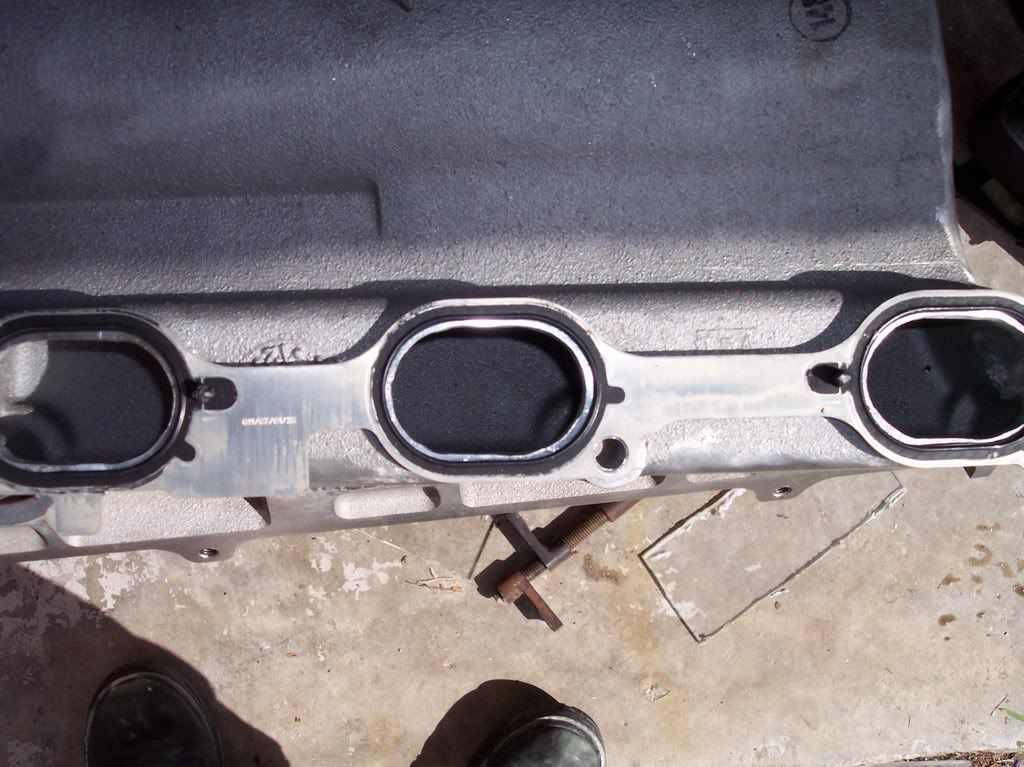
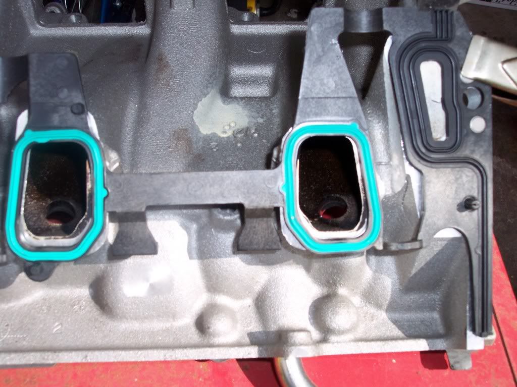
                      Looking at the LIM, there is a lot of work to do. The UIM won't be so bad since it's just thin aluminum to clearance.


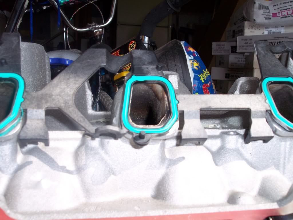
                      And what do you do in a situation where the gasket extends to the inside of the port? I just noticed what looks the stain from fuel puddeling there. should I trim the gasket a bit, or just leave it?...

                      Links:
                      WOT-Tech.com
                      FaceBook
                      Instagram

                      Comment


                      • #26
                        Actually scratch the last question, with the heads and LIM bolted together, the gaskets line up with the center port more like the others, and sill going to have to remove some material from the floor.
                        Links:
                        WOT-Tech.com
                        FaceBook
                        Instagram

                        Comment


                        • #27
                          Bell-mouth the plenum ports too. Be careful of the LIM gasket matching, as the gasket when bolted down shifts and is in a different spot. When it's just lying on the intake it's not in it's final position until the rubber is smashed down tight.

                          What do you guys use to port? I have an air die grinder and a stone wheel, but it takes forever. Granted I only have about 6 secs before the air tank is empty, but even then it doesn't take much metal off...
                          sigpic New 2010 project (click image)
                          1994 3100 BERETTA. 200,000+ miles
                          16.0 1/4 mile when stock. Now ???
                          Original L82 Longblock
                          with LA1, LX9, LX5 parts
                          Manifold-back 2.5" SS Mandrel Exhaust. Hardware is SS too.

                          Comment


                          • #28
                            I plan to radius the inside of the plenum. Going to see if I can get the inside of the TB neck smooth, too.

                            For grinding, I will be using my RotoZip. It never runs out of air I have a nice radiusing but, I'll get pics up later. When I get close, file is nice on aluminum.

                            I have strips of sand cloth to get the inside of the runners, and am going to make a drum with a long extension to get the rest.

                            Too bad I didn't have time to sit down and put this into the CNC while I was at it. Then they all would have a perfectly smooth finish, and all would be exactly the same. Some areas would still have to be done by hand regardless.
                            Links:
                            WOT-Tech.com
                            FaceBook
                            Instagram

                            Comment


                            • #29
                              Originally posted by ForcedFirebird View Post
                              I have a nice radiusing but, I'll get pics up later.
                              Please keep these to yourself, and your wife.
                              -Brad-
                              89 Mustang : Future 60V6 Power
                              sigpic
                              Follow the build -> http://www.3x00swap.com/index.php?page=mustang-blog

                              Comment


                              • #30
                                Originally posted by bszopi View Post
                                Please keep these to yourself, and your wife.
                                I meant bits, you butt!


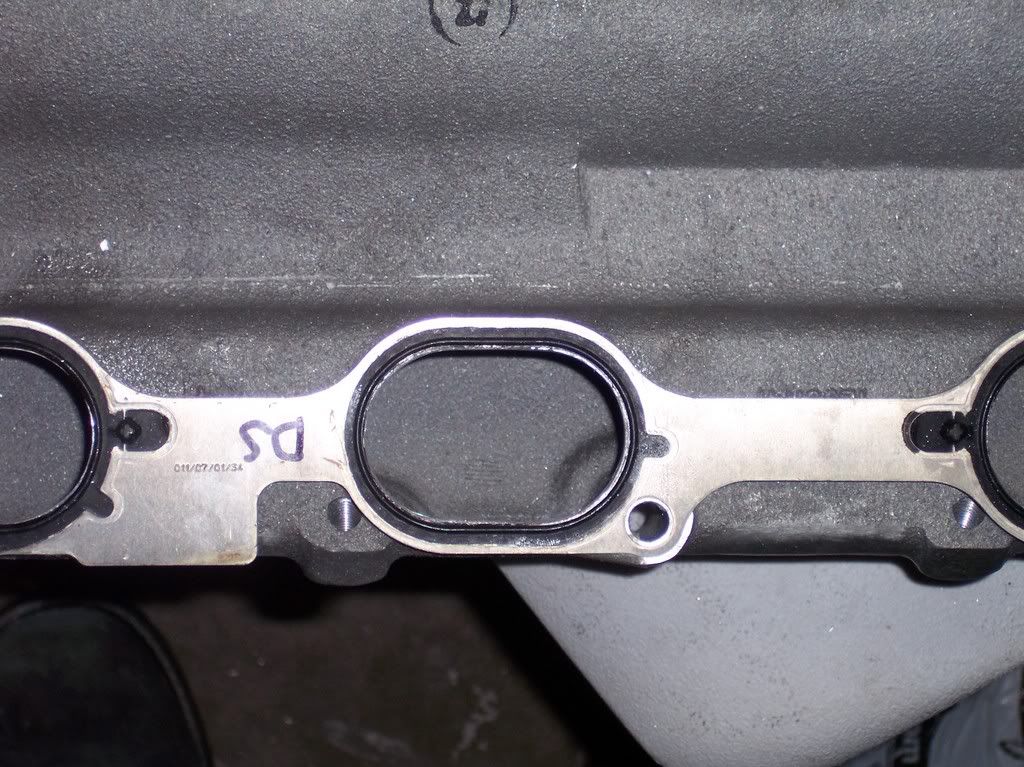
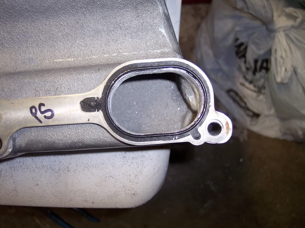
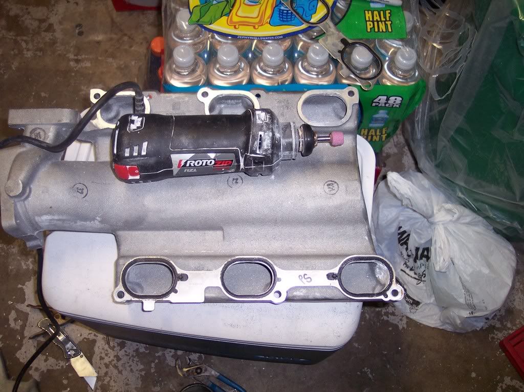
                                Got the UIM done tonight. Spent about 2hrs on it total. First a gasket match, then radiused the inside...


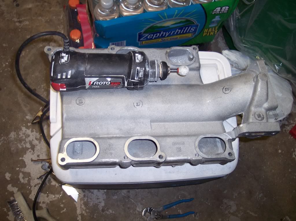
                                Changed bits. Couldn't find my outside radius stone, so I went with a sphere...


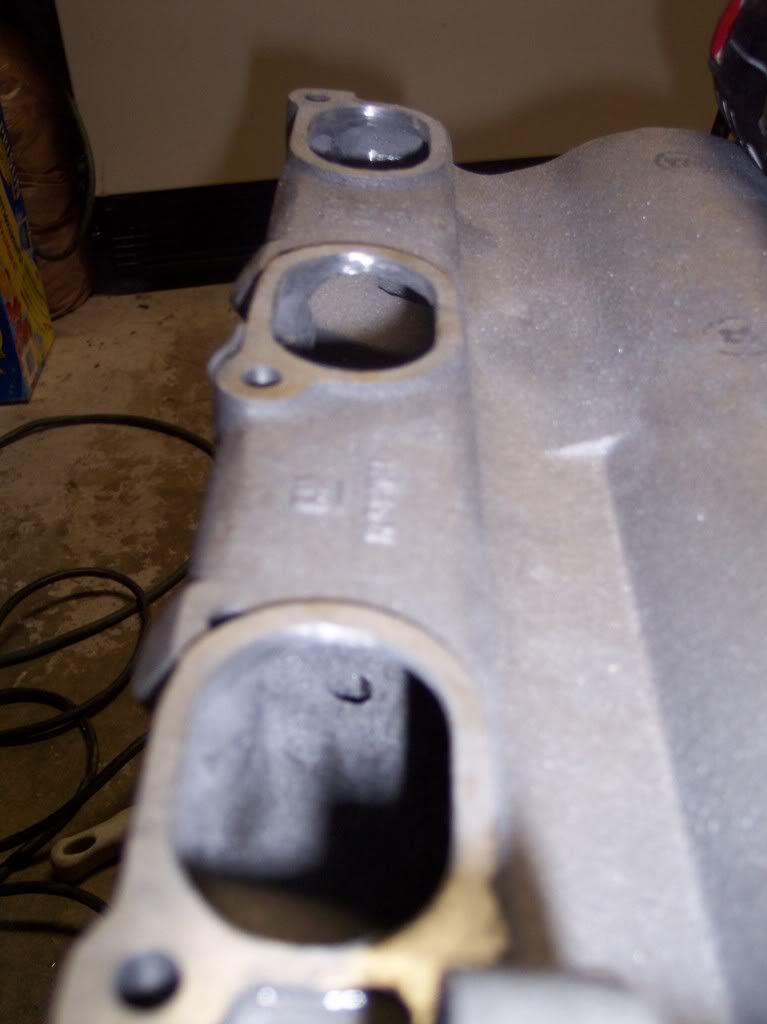
                                ^^^ tough to take a pic of the inside!
                                Links:
                                WOT-Tech.com
                                FaceBook
                                Instagram

                                Comment

                                Working...
                                X