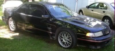
Ok, I got the motor back in the car and sounds great. However I am having an issue with the alternator/charging circuit. Alternator is outputting 14+ volts at the alternator. alternator idiot light is on and I get 11.5-11.75 volts at the battery. Battery is new and I had it load tested before I left the store. Alternator is used but was tested at two different shops and they verify it is working correctly. I meticulously cleaned all the wiring to block grounds before putting the engine back in the car. Battery cables are clean and in good shape. Contact at alternator is good. I also replaced the starter with a "new" rebuilt.
The one questionable thing I found is when checking the continuity of the output circuit I get a reading of .022 ohms. IIRC you want a reading of .5ohms and a failed circuit should yield an infinity reading. Does this indicate the problem?
Every on car diagnostic site refers to a in line fusible link that will keep the battery from charging if the circuit tests open. I went on line at Mitchell to get a wiring schematic. One diagram of the power distribution system shows a fusible link (10 GA Brown) between the alternator and starter selenoid. However, when I look at the diagram for the charging circuit no such fuseible link is on that diagram. Does anyone know if there is a fusible link and where it actually is on this car?
Also, the connector coming from the alternator in the schematic for an 03LS shows 3 wires: orange going to the 10A GEN BATT fuse, red going to the GEN Terminal L Control on the PCM and Grey going to GEN terminal F Input on the PCM. My car only has the red and orange wires and only those two metal connectors in the plug. Anyone know what the F Input is for and is that a problem? Why does the diagram show a grey wire and my car (03 supposedly matching the wiring diagram) doesn't?
Other info that may be pertinent: Alternator is the Bosch 2nd generation 105 amp.


Comment