Announcement

Collapse
No announcement yet.

How to R&R an F-Body 3.4L V6 via the Bottom

Collapse
X
 
  • Filter
  • Time
  • Show
Clear All
new posts

  • #16
    Originally posted by ForcedFirebird View Post
    Bob. I didn't go crawling under the car like that! lol. It was needed to be picked up that high to pull the motor out from under the wheel wells, and with the drivetrain on wheels, the engine hoist was in the way of pulling it out the easiest way - the front. If I had more lateral room, the hoist would have stayed attached and pulled it out the side, but had the ForcedFirebird on one side and the lawn to deal with on the other
    John...No Problem... I wasn't being critical of you...you are alive and well because invariably... know what you are doing... but since I have a responsibility with posts like this that involve suggesting things that people might be able to do relating to what I am about to try... I always have an over-arching concern for their safety... and thus my suggestions for being as careful as possible when attempting anything I might be encouraging others to try and do.

    YOU would never get under that F-Body... but in the absence of telling people NOT to do so...there is always someone who may not understand the inherent danger in doing so. I don't think I have ever seen you getting any safety issues wrong. As for me... I believe that women and children may be careless...but not men...and so I insist on reminding the folks interested in my posts to keep their wits about them and not engage in anything that might cause them or others to be harmed or killed.
    Last edited by 60dgrzbelow0; 11-24-2009, 02:17 AM.

    Comment


    • #17
      Okay... Getting back to the dirty little job of trying to make something robust and strong enough to comfortably and safely support and hold the entire weight of the K-Frame Member, the entire front suspension and the engine and transmission, this morning I went back to the Best Metals Salvage Yard and purchased a 48" X 48" X 1/2" thick Welder's Table equipped with four tall, tubular steel legs for around $50.00. That may seem like a bit too much to pay for "Scrap Metal" for this project... but since I have needed a Welder's Table for some time now...I can kill two birds with one stone. My plan is to cut the table in half with a torch and make the roll-around Engine and Transmission carriage as a 24" X 48" segment with sturdy, Ball Bearing Wheels and ...and still have a matching segment to weld on the two pipe legs from the other segment to make a narrow Welder's Table, as well. The photos and videos showing some of the difficulties which still must be overcome. My Oxy-MAPP Gas Cutting Torch was insufficient to create and sustain enough heat to cut more than four inches deep along the split-line between the two halves of the heavy steel table (it weighed out at 328 Lbs) Tomorrow morning... as long as the local welder's supply will fill a tank sold by Harbor Freight...I'll spring for a small, compressed cylinder of Acetylene Gas and finish separating the two halves of this large steel plate. Then, Ill either drill holes for the heavy duty carriage wheels and mount all four wheels or MIG weld them in place. I'll also drill out a centered hole on the interior edge of one half of the large table and either attache a cable, a rope or a wooden "T" bar to pull and guide the cradle under and around into the proper position. More to follow ... with new Photos and Videos here:

      Store your photos and videos online with secure storage from Photobucket. Available on iOS, Android and desktop. Securely backup your memories and sign up today!
      Last edited by 60dgrzbelow0; 11-24-2009, 02:19 AM.

      Comment


      • #18
        Originally posted by SofaKingWeToddDid View Post
        shoulda wentat night time with some hand tools and shit, you coulda got that motor for free!!

        After I sold the tranny and the accessories I didn't need I only had $50 in it.
        87 3.4 4x4 blazer
        3 inch body lift, t-bar/shackle lift, 31x10.5s

        Comment


        • #19
          Man....I pulled the engine out of the 94 Camaro I had and it came out from the top, with the tranny attached! It was a PITA going back in too! If I would've had the CORRECT EQUIPMENT it would have been a whole lot easier. It sucks working in the dirt too.
          sigpic
          94 Firebird 3.4 DD
          252000mi. All original

          Comment


          • #20
            Originally posted by Firehawk94 View Post
            Man....I pulled the engine out of the 94 Camaro I had and it came out from the top, with the tranny attached! It was a PITA going back in too! If I would've had the CORRECT EQUIPMENT it would have been a whole lot easier. It sucks working in the dirt too.

            Done mine in the yard in front of the shop. Dad's POS toyota 4x4 was in the open bay so I had to do it where I had to. I'm glad I didn't have to put it back tho.
            87 3.4 4x4 blazer
            3 inch body lift, t-bar/shackle lift, 31x10.5s

            Comment


            • #21
              The Steel from the Welder's Table is Prepped...

              As usual... Visual Cliff Notes provided for those just wanting the "Short Story"

              Store your photos and videos online with secure storage from Photobucket. Available on iOS, Android and desktop. Securely backup your memories and sign up today!


              Okay... I dodged a Dollar Bullet this morning by coming up with a more practical solution to cutting through that damned Welder's Table... My suggestion is that if you decide to follow this example in "over-building" your own cradle, get some 7" (Thin) Aluminum Oxide-Carborundum Cutting disks and mount one (it will only take two do cut about four feet of half-inch Cold Rolled Steel Plate) and have at it!

              The only thing you have to be careful of is to remember to carefully manually lift the Blade Guard or the back of the 7" + 2.5HP Circ Saw will catch on the narrow edge of the steel plate. Wear ANSI approved equipment when doing all of this (Welder's Leather Apron and Gloves...Full Face Mask...Heavy Jeans and a Long Sleeved Shirt). Mind how you set your work up to remember your "Spark Trail" is long, very hot and with accumulation of waste metal "scabs"...capable of setting your clothing on fire...(and that can of Gasoline on the floor right behind you). I recommend that you do this job outside using grounded tools and extension cords and keep a Fire Extinguisher and a Water Hose nearby.

              After you are set up to work safely... Use your grinding-cutting tools with BOTH hands. With steady pressure and some patience in watching your "Scratch Line" for guidance, you should wind up with nice, clean cut edge. DON'T FORGET TO GET SOME SOFT EAR-PLUGS TO PROTECT YOURSELF FROM GOING DEAF!. And the last prepping suggestion I'll make is...have some pity on your neighbors as to what time and for how long you intend to work on your steel-shaping project.

              To prevent getting permanent nerve damage in your hands and arms from the constant and excessively high frequency vibrations... take a break every fifteen to twenty minutes... stretch your legs and your back and go TAP and get a cold drink. Leave the alcohol for AFTER...because at the end of the day, you'll want to have all ten toes and ten fingers and both of your eyes...right? Watch for loose or hanging clothing and garment straps from getting snagged and rolling you up into something spinning faster than the redline on your car engine...If it happens...if you are still conscious ...or even still alive...you will NOT be able to turn off the thing that just inhaled some of your body parts!

              Once the major cutting of all that steel is done, remember to dress up the edges of both sides of the cut work for razor sharp edges and some left-over "Razor Blades" that can shred your fingers and Blue Jeans if you get snagged on any of them. Get a Yard Magnet on a Stick and glom all that sh*t up to prevent it from either being ingested by the cars in your driveway...or worse yet...wind up in your Kids' bare feet...or even a tire or two. It won't hurt to clean up the look and feel of the finished cut edges with a Bastard File and that pretty much takes care of the problem.

              The reason I chose the dimensions of 24"W X 48"L X 1/2" for this job was that I measured well up into the splayed legs of my Cherry Picker Hoist to make certain that the outer edges of my "Engine-Tranny Tray" would not be prevented form getting properly positioned under the K-Frame Member and all that is behind it... by bashing into the legs of the Picker and finding it impossible to get it properly placed under the car.

              The nice, flat steel surface allows for some "fudge-factor" if the assembly requires adjusting to get at the various mount bolts from the Transmission Cross-member Support Bolts and up front where the lower bolts must be removed along with those holding the strut towers in place. The same idea applies when the whole apparatus has to be wheeled back in place for the return trip with a new motor in tow.

              My choice of wheels might be considered a luxury at $12.00 a pop for the assembly...but they roll so free and easy and will never bind as long as all three grease fittings are used to prime the double roller ball-bearing sets with grease to make turning and adjusting all that weight much, much easier to do when it comes time to align everything.

              Don't forget that the other half of steel plate is also 24" X 48" and is just the right size I needed for my own "Real" Welder's Table. When the four legs are leveled, tacked in place and welded symmetrically back on the excess piece...I'll finally have a decent one. The other thing not known to all you as of yet is that back in the days when I was a competitive shooter, I used to mine the berms and safety banks behind the ranges, finding literally tons of Bullet and Rifle Lead. After smelting the dirt, old brass and rifle bullets out of the molten mess... I would pour the remaining lead (nice and "Linotype' hard for comp shooting...with minimal "bullet-wipe" and very consistent ballistics as a result) into corn cob ingots and save the stuff for future bullet making.

              Even after thirty years or so... I still have several galvanized garbage cans filled with these lead ingots. The problem though is that they sit on a practically immobile steel wheel cart that is a Stone Bitch to move or get around in the back of my garage. But when the Engine Swap is done...I'm thinking about adding a third set of the spinner wheels to the mid-section of the Engine-Tranny Tray... and then use IT to caddy around all that heavy lead stuff.

              Tomorrow... I'll take a scale digital image of the bottom side of one of the wheel brackets and print up four of this image to tape in place on the four corners of the steel bed and then drill me out the sixteen holes with my drill press. I'll just find the right height on each corner and set the edge of the steel plate on top of the Drill Press Table and that will make very quick work of drilling all 16 holes, very straight and true (pics to follow). Then I'll drill two centered and aligned holes in tandem about one inch in from the edge what will be the "Front", and the left and right sides of the Tray...and bolt in two sturdy "Eye" Hooks on the under side of the Tray at all three positions. Afterward... I'll take the "Bag-A-Boltz" that include round head tops for the top and large flat and locking washers with lock-nuts and after aligning the wheels ...Ill bolt everything up and tighten them all down. The tray will be reading for a test drive after that...but I'll be careful not to sever a toe or two when flipping it over at 185#s in weight and then onto the new wheels for a spin around the driveway.

              These three "Push-Pull" positions will allow me to attach either a Nylon Pull Ropes...or... I have an idea in mind to make a long "T" Handled Re-Rod Push-Pull Bars that will slide inside the two "Eye" Hook holes on any of the three sides and allow my Spotters the chance to move and adjust the entire Tray with excellent control...without having to break their backs or mine...or be too close under the car to do it... (pics to follow).

              It was a very gloomy and rainy day today... but my Driveway Weather Report had a little Sunshine to appreciate when this Damned Job was finally done.

              Store your photos and videos online with secure storage from Photobucket. Available on iOS, Android and desktop. Securely backup your memories and sign up today!
              Attached Files
              Last edited by 60dgrzbelow0; 11-25-2009, 11:34 AM.

              Comment


              • #22
                those pontiac rims look good on the white camaro.
                sigpic
                99 Grand Am GT
                3400/3500 -Solid trans mount--TCE 65mm T-body---85mm LS2 maf---1 1/4' TCE intake spacers with 3400 upper--SLP Catback with flowmaster 80--TOG headers
                Modded 3400 lifters with LT1 springs---Comp Cams 26986 Springs
                1357 cam 227 233 .050 dur
                515 515 lift 112 lsa
                15.232@88.85mph on stock 3400---New time to come


                Comment


                • #23
                  Originally posted by geldartb View Post
                  those pontiac rims look good on the white camaro.

                  Gel...

                  JSYK...

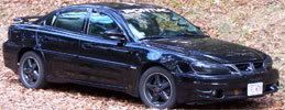
                  The Rims on my son's Black 94' Camaro depicted in the length comparison photo showing the Engine-Tranny Tray vs. his car in profile...are Stock as a Clock Camaro "Salad-Shooters"... AFAIK ... The Pontiac Firebird F-Body Fourth Generation Carline Series from 1993-1995... did not sport them. Please correct me if I'm wrong..

                  Comment


                  • #24
                    I believe he was talking about Paul's car. The rims were never mounted, just stuck them in the wheel wells so the city didn't catch on that there was no drivetrain in it lol. Rims going on the car are magnesium zr1 wheels

                    Bob, if you ever watched me work, you would have a hear attack haha.
                    Last edited by ForcedFirebird; 11-25-2009, 12:45 AM.
                    Links:
                    WOT-Tech.com
                    FaceBook
                    Instagram

                    Comment


                    • #25
                      Originally posted by ForcedFirebird View Post

                      Bob, if you ever watched me work, you would have a hear attack haha.
                      rofl

                      93 Firebird 3.4
                      Pacesetter Headers, Flowmaster 80, Comp 1.6 RR,Cloyes 2x Set, P&P Heads & Intakes, Custom Cam, Holley FPR, Ram Air Intake, Posi Rear w/3.42's & Disk Brakes.
                      Cam and Heads by 60Inclusive.com

                      Comment


                      • #26
                        Originally posted by ForcedFirebird View Post
                        I believe he was talking about Paul's car. The Rims going on the car are Magnesium ZR-1 Wheels
                        Oh.... (Sorry about that, Gel... my mistake...)

                        Originally posted by ForcedFirebird View Post
                        Bob, if you ever watched me work, you would have a hear attack haha.
                        LOL... You Funny Man, You...

                        Originally posted by ForcedFirebird View Post
                        The rims were never mounted, just stuck them in the wheel wells so the city didn't catch on that there was no drive train in it... lol.
                        As for any palpitations I might suffer... they would only come from, "Standing in the Presence of The Master..." and perhaps from the other problem you just solved for me! Your suggestion about putting the unmounted rims under the car to disguise the fact that the car is not drivable is BRILLIANT. I have already had the County Inspectors ride my Keister for having Scott's car up on the car Ramps too long when I was doing his LS1 Brake Conversion... so I was worried about them coming back when the neighbors spied me doing the engine swap. I'm hopeful to get this done all in one day...but you know how that can go... with unintended interruptions and delays... so once again... Thanks John!
                        Last edited by 60dgrzbelow0; 11-25-2009, 10:54 AM.

                        Comment


                        • #27
                          Okay...

                          Went to Loew's this afternoon and decided to pick up two more sets of 5" Full Roll-Around Wheels after thinking that being able to move the Engine-Tranny Tray in any direction on all points of a 360 Degree Radial made more sense than only having the ability to adjust in this manner on the two front wheels. There will be Three (3) Sets of Wheels now instead of only two ...because I thought that the longer length of 48" might flex downward enough if the weight of this entire group of machinery might be enough to bow the flat steel plate all the way to the deck. This way...I've eased my mind on that score.

                          Also...I have acquired two more "EYE" Hooks in order to mount one on either of the long sides of the Tray with also having one in the front so that all three can be used to manipulate the Tray with great precision...without putting my Spotters in any jeopardy. I simply have to tie nylon ropes to the three "EYES" and then thread the ropes through 1/2" by 4' lengths of White PVC pipe... and this way the Tray can be pushed, pulled and adjusted on three vectors when it comes time to lower the car back onto the entire assembly with the New Motor more easily to attain the necessary alignment needed to get all the K-Frame Bolts re-installed and the Shock Struts into the Towers lined up right. As Robertisaar might say..."Maneuvered? No...McGuyvered? Yes!"
                          Last edited by 60dgrzbelow0; 11-25-2009, 11:56 PM.

                          Comment


                          • #28
                            The Follow-Up Engine-Transmission Cradle Assembly Images and Videos can be seen here:

                            Store your photos and videos online with secure storage from Photobucket. Available on iOS, Android and desktop. Securely backup your memories and sign up today!


                            Okay...

                            I finally managed to find the time and the inclination to get the 24 of the 27 necessary holes drilled into that heavy plate steel platform that the Engine and Transmission will soon be resting on. I'm glad to have had a portable Craftsman Drill Press because drilling out 27 holes (4 per wheel unit X 6, plus the three needed for the EYE Hooks) through 1/2" gauge cold-rolled steel ...is harder on your muscles, your hand drill and the drill bits that could be ruined while trying to make them all symmetrical and true than you might think at first blush... assuming of course that your back holds out to the end of the job if you choose to do this the Hard Way.

                            And so... following on with the design of the "Jack Stand Towers" using the 2" X 4" X Whatever is required in the various lengths... in this case I needed to design and build a platform that would support my Drill Press well enough not to have it "Golly-Wogging" down my driveway (this phenomena happens because so much of the mass and weight of the machine sits so much higher than the lighter wooden base it is resting upon that it tends to "walk" forward or backward with increased pressure on the drill bit)...and yet , still be light enough to lift and adjust from one position to another around the perimeter of the steel plate to efficiently get all of the holes drilled... I constructed what was needed as a 9" X 12" stand that I just clamped to the lower table of the Drill Press so it would not tend to walk off while vibrating so much when operating the drill. At various times during the drilling process, I used a Shop Magnet to collect the spall shaped, razor edged cuttings and later used a magnet wand to pick up every last bit of the stuff before it can migrate into anybody's bare feet or get ingested in the engines of our cars. Naturally... having an Oil Can nearby to lube the drill hole and cool off the drill bit helps ...regardless of which drill tool you choose to do the job.

                            My decision to use six wheels instead of four feels better because I'm confident now that now matter how heavy the entire assembly turns out to be...even if its over 1,500 lbs... this Engine-Transmission Cradle will bear up nicely under all that weight and free-wheel well and truly when being moved out from under the car and when being slid back in place to lower the chassis down on top of the works.

                            I have some additional questions though either for John (Forced Firebird) or anyone else with experience in doing this "Factory Engine Removal" as follows:

                            (1) Regarding the "...removal of the wire harness that feeds through the Firewall near the Passenger Side Kick Panel"... Why is it necessary to remove ANY of the electrical/electronic harnesses when what I have planned is to Tag/Label each and every connection between the indigenous engine and the engine compartment hook-ups? I'm confused as to whether your method involved(s) dropping the Engine and Transmission ...while leaving the entire set of harnesses still attached to the motor.

                            (2) How long did it take to remove and replace the old engine with new after it (and the transmission) was slid out from under the car? I'm not looking to break any records here (I'm much to much of a realist and a cautious mechanic for any of that nonsense) ...but I am interested in how best to use the ease and uncommon accessibility to all the parts and pieces. I noticed John... that after you separated the Transmission/Bell Housing from the Engine... that you installed the Motor on an Engine Stand... with the Tubular K-Frame attached... partially supported by Jack Stands on the out areas. I would much rather work on this entire mechanism at anywhere from waist to chest high since it beats crawling around on your hands and knees on the floor while trying to use a Torque Wrench and do other mechanical things without any comfort or control. I've been so completely satisfied with the design and build of the Wooden Scaffolds that what I might wind up doing is making three more of them ...somewhat taller ...and use two in the front to support the Engine/ K-Frame and Front End Section and use the third one to support the Transmission and simply position everything roughly centered in my garage with the Parts Table and Roll-Around Tool Chest on the periphery to allow me the chance to move around all this hardware and get the work done more smoothly.

                            (3) I'm curious about how the Lift Chain/Harness was arranged on the White Pontiac Firebird to lift the car from the narrow area in the front of the car, John. The images of the man with the Red Z-28... showed that he snaked his two chain/hooks in and around the "Horns" in the left and right sides of the front end. Is this the same area you set yours up with?

                            Just a word about Safety...

                            Anyone who thinks that all this preparation and aforethought is a complete waste of time should visit the writings of Sun Tzu (The Art of War):


                            17. Thus we may know that there are five essentials for victory:
                            (1) He will win who knows when to fight and when not to fight.
                            (2) He will win who knows how to handle both superior and inferior forces.
                            (3) He will win whose army is animated by the same spirit throughout all its ranks.
                            (4) He will win who, prepared himself, waits to take the enemy unprepared.
                            (5) He will win who has military capacity and is not interfered with by the sovereign.

                            In my experience... thinking about what you are about to do that is both new and dangerous... before you can make any serious mistakes in judgment in the doing of it... just makes good, common sense. When I finally have a chance to separate that Old and Tired Motor from my Son's Camaro... I don't want any loss of life or limb to hamper what should be the pleasant experience of putting what amounts to a Brand New Engine back in its place. I also want the opportunity of actually ENJOYING the 'doing' of it all... without having to lay on my back, pinned under a car and having those 'dirty, little balls of grease' dropping into my eyes while reaching up into the guts of the car body and trying to bolt or unbolt parts I have to visualize to get either on or off of the car/engine. It is this very uncomfortable image that comes to mind and lets me know that the time I'm taking now to get ready to do this job right is time well spent.

                            Store your photos and videos online with secure storage from Photobucket. Available on iOS, Android and desktop. Securely backup your memories and sign up today!
                            Attached Files
                            Last edited by 60dgrzbelow0; 12-02-2009, 07:39 PM.

                            Comment


                            • #29
                              For a few images of what follows in greater detail...Please visit here:

                              Store your photos and videos online with secure storage from Photobucket. Available on iOS, Android and desktop. Securely backup your memories and sign up today!


                              Unless somebody squawks on this idea as being an impurity in the specificity of this thread subject matter... from now on... until the engine R&R is completed and the motor is broken in and running... I'm going to include the remaining Engine Assembly Procedures as part of the project with all my usual "adornments" of photos and "How-To-Videos" when appropriate and perhaps useful in many other applications of these sub-installations and repairs. What remains to be done to complete the Short Block are the following installations:

                              1. The Engine Heads, Spark Plugs. (wiring, coil packs and ICM hook-ups will follow....and of course...The two Valve Covers )
                              2. The Hydraulic Flat Tappets, Push Rods and Roller-Tipped Rocker Arms.
                              3. The Upper-Lower Intake Manifolds, Throttle Body. EFI Manifold, EFIs and Upper Cam Sensor.
                              4. The Timing Cover, 24X Sensor and Water Pump and Harmonic Balancer and Crankshaft Drive Pulley.
                              5. The Oil Pump (and....LATER.... The Oil Pump Drive/Rod assembly)
                              6. The Oil Pan (Gasket and sealing issues will also be dealt with).
                              7. The Engine Pre-Lubrication. (Finally... I'll get a chance to try out my OTHER Frankenstein Invention..."The OPPOT"- (Oil Pump Pre-Oiling Tool)
                              8. The Flexplate/Flexplate "Washer" and Flexplate ARP Bolts.
                              9. All the 'Other' sensors... Knock, 7X...etc...
                              10. Motor Mounts, Front Accessory Brackets...and Misc. stuff
                              11. Pacesetter headers and EGR Valve, O2 Sensors, etc.

                              Sooner or later... I'm going to get the "Razz" (Raspberry) from some experienced mechanics who will tell you that, "Jesus Palomino, Bobby...You don't have to worry about it THAT much..." when comes to the cleanliness of the parts and pieces in your engine re-assembly. Perhaps. But to my way of thinking...Cleanliness is next to Godliness because when you have eliminated all that old dirt and grime from the parts and pieces that either will not or cannot be replaced with anything Brand New... then making them spotless eliminates one more thing you have to worry about: Unintentionally Contaminating a New or Rebuilt Engine. I mean think about it... Would you wash your feet...and the put on Dirty Socks? Hell NO!

                              How to Clean and Prep Old Valve Covers:

                              Okay... Today's example of this serves to kill three birds with one stone, The insides of the Valve Covers on this little V-6 Engine were exposed to the sloshing action of millions of cycles of pumped motor oil... much of which became dirty over time from ingested mung being breathed in and making its way past the ever loosening rings on each piston. They were also exposed inside to all that unburned fuel and burned by-products of incomplete combustion that included noxious, dirty and oily vapors that serve to literally varnish the insides of the covers over time and in this case...at nearly 100,000 miles...they have become "less than sanitary" inside... to say the least.

                              But... with the right sized closed container and concentrated cleaner... you can easily bring back the newness and cleanliness of these important and protective sheet metal containers...without breaking your balls with using dangerous solvents and cleaners and more elbow grease than you might think to dedicate to these three pieces of "Tin" (The Third Man (bird?) in this story is of course...the Oil Pan...but THAT is for another story)

                              In my case... I use a Very Large Coleman Cooler as my sealed container to hold the fresh batch of a 50/50 mix of my favorite Concentrated De-Greaser and Cleaner called "Purple Power" and plain water. I simply fill the cooler to a level at least one third as wide as the piece(s) I need to cover with the stuff...and after removing any plastic or rubber removable parts or grommets...I just submerged the two Valve Covers into the stuff...close the lid...and walk away.

                              Since I'm NOT using anything Aluminum...I don't have to worry about bad things happening to the Mild Steel Covers and I don't have to be concerned that the Black Cover Paint will be dissolved either. Three or four days later... I checked on the progress of the two covers and decided to leave them in a bit longer since I was not in a rush to get them ready for installation. After five days... I pulled out the two covers...then hosed them off in the driveway and IMMEDIATELY sprayed them down with some liquid wrench to prevent the normally munged up but essentially rust-proofed via the old oily junk on them, inner surfaces from rusting up in very short order.

                              Then ...after getting my materials together I did the following:

                              1. Carefully Scraped and Cleaned the Inner Race areas of the two Valve Covers of all traces of any and all old adhesive and Cork Gasket material.

                              2. Sprayed both covers down very well with Brake Cleaner.

                              3. Applied a thin layer or coat of NAPA Hi-Tack Gasket Sealer to the inner race of each cover and allowed them to sit for a few minutes.

                              4. Applied a thin layer or coat of NAPA Hi-Tack Gasket Sealer to the matching sides of the cork gaskets and allowed to sit for a few minutes.

                              5. Carefully inlaid both Brand New Cork Valve Cover Gaskets while aligning the mounting holes and mating surfaces between the two surfaces. If you were not careful during the application of this stuff and you have drips and drabs of the NAPA Hi-Tack stuck on everything...not to worry...Spray some Brake Cleaner on some White Tee Shirt material...and it will come off the surface of the Cork Gaskets...your fingers...and here is another tip...wipe down the outside of the Hi-Tack Container too...and the next time you reach for it...you won't stick to the can!

                              6. Finally...and this is the part that gets skipped too often... Take the rounded side of a 1/2" Box End Wrench and use it to gently work the Cork Gasket into a fully seated position and get all the air bubbles out between it and its contact with the cleaned up metal rail surfaces.

                              7. After they sit for a half-an-hour or so...spray down the exposed inner metal surfaces with either WD-40 or Liquid Wrench.

                              8. If you cannot install these covers immediately... Save yourself the grief and the time and effort it will take to clean them up all over again after leaving them laying around until they have to go back on the new or re-built engine heads...by simply WRAPPING THE VALVE COVERS IN SOME SARAN OR CLING WRAP! Also...WD-40 WILL evaporate over a short time frame!

                              9. Two Days... or even Two Years Later... when you are ready to install those "Freshened Up" Valve Covers... just unwrap those Puppies...and Bolt Them On... No additional cleaning or prep is necessary.

                              Store your photos and videos online with secure storage from Photobucket. Available on iOS, Android and desktop. Securely backup your memories and sign up today!
                              Attached Files
                              Last edited by 60dgrzbelow0; 12-06-2009, 07:40 PM.

                              Comment


                              • #30
                                For the Final Images and Demonstration Video of how the construction of the Engine-Transmission Cradle and Wood Support Towers turned out... Please visit this site:

                                Store your photos and videos online with secure storage from Photobucket. Available on iOS, Android and desktop. Securely backup your memories and sign up today!


                                Okay... The cold rains finally stopped and after the Sun broke through the clouds long enough to do any good, I rolled the Engine-Transmission Cradle out onto the driveway and finished installing the remaining two wheels for a total of Six (6) and swapped out one(1) of the four (4) bolts for each of the six wheels holding them to the 1/2" x 48" x 24" Plate Steel platform for Six (6) "EYE" Bolts instead of using only three (3) positioned at the two sides and dead center on one of the long ends of the cradle.

                                It occurred to me since last working on the item that I would need the ability to move and control the platform from any number of positions, for any number of heavy lifting and transporting of engine/transmission/rear-end components in the future, so I might as well anticipate the need and put Control Points at all corners and both sides as well. After I tied on two lengths of rope and fed the lengths through two five foot pieces of white PVC pipe, I pulled the ropes tight and just wrapped the cord around itself to make a handy place to grip on the far ends of both pipes. I shot a short video to demonstrate how this last addition and idea worked out to make the moving of this nearly 200 lb Engine-Transmission Cradle was and how easy it will be to control when moving the Old Engine and Transmission out...and the New Engine with Transmission into place for the re-installation that is yet to come.

                                The next installment will cover the re-brazing of the Oil Pump Pick-Up Tube to the Oil Pump and perhaps the installation of that assembly onto the Engine. I'm fighting some abnormally inclement weather and very windy days which make working in my garage too much like a dungeon with the garage doors being closed...but as soon as those things level off...I'll be 'turning to' on working with the last of the Engine Assembly.

                                Store your photos and videos online with secure storage from Photobucket. Available on iOS, Android and desktop. Securely backup your memories and sign up today!
                                Attached Files
                                Last edited by 60dgrzbelow0; 12-06-2009, 07:35 PM.

                                Comment

                                Working...
                                X