Announcement

Collapse
No announcement yet.

Ignition problem with 3100 to 3500 swap w/ no code

Collapse
X
 
  • Filter
  • Time
  • Show
Clear All
new posts

  • #16
    In looking at the wiring diagrams, the 24X sensor does get ignition power, but it comes directly fro the PCM through lead #70, The 7X sensor is the one that plugs directly into the ignition control module and it is a two wire system that generates somewhere between .5 and 2 volts AC. The 7x does not get external power.

    I marked the reluctor wheel at the various firing positions and I pulled the fuel pump relay to limit the fuel flow. Shining the light on the wheel and trying to figure out what is happening is tough, but #1 was firing right at TDC. Here's where it get weird: #2 looks like it usually fires at #2 TDC, but I know I saw it fire a couple times at #1 TDC. If so, it is firing 60 degrees advanced, and that does make it hard to crank. So, it may come down to a defective ignition module.

    I know the car was running OK when the cam broke and caused the death of the original engine. The car has not run in a year, but the electronics should not care. I took it out and see that it consists of 3 coil packs than slip onto the ICM base. The only thing I can figure at this point is that the electronics portion has a bug that is causing it to fire more than one pack at the same time.
    Last edited by kerno; 02-24-2010, 12:06 AM.

    Comment


    • #17
      goto basics,
      Will start with or with out 24X so dont worry about that one.

      You have fuel pressure and Injector pulse and Rpm, so the ICM and PCM are seeing a signal from 7X sensor.
      Issue could be dad 7X sensor, ICM or engine mechanical.

      You rebuilt this engine? Timing chain correct?
      If the sensor is lined up good, I would replace ICM with a known good module and recheck.
      As of April 2
      3rd Gen Cavy has 3500 Installed!
      ----------------------------
      Engine: 2006 SV6 3500 LX9
      Trans: 2002 Getrag F23 5speed
      Pcm: 2001 Impala La1 3400 with complete Engine Harness.
      Injectors: #36 GTPs
      TB: 65mm TCE
      Maf: 1999 3400 Montana.
      Adjustable TCE Fuel pressure Regulator
      Walbro W1 255 pump from Racetronix.
      Beverages: Ice Cold CANADIAN.

      Comment


      • #18
        The engine came with the complete tranny and front sub-frame from 1 2006 Buick Terraza. It had been hit on the right front corner, but the only thing hurt on the engine was the front cover, where there was a crack in the water pump housing. The thing had to be running when it was crashed. I watched the valve event last night as I turned it over with a breaker bar and the intake closing and exhaust opening were very close to symmetrical about TDC, so the cam and chain is OK.

        The culprit to me is the out of sequence firing of the plugs. There's no way #2 should ever fire at #1 TDC, unless the ignition module was randomly commanding the wrong coil pack to fire or firing two at once. The great thing about having the Wot-Tech reluctor wheel on it is that checking timing is a snap. I saw the flash clear as day when the timing light was on the #2 lead and it lit up my white paint at #1 TDC. So, I'm going to have couple beers tonight, instead of flogging on a project that I know way more about than I ever wanted to. I took lots of pictures and will post a detailed swap thread - once I get the thing running.

        Comment


        • #19
          IMO it appears there could a false signal causing the ICM to start the firing sequence multiple times during a revolution. That would cause the high/low RPM reading and firing at the wrong time. The false signal could be caused by noise picked up by the CPS~ICM wires or possibly the CPS location. Is the CPS centered on the trigger wheel? It doesn't have to be perfect but the metal tip of the CPS should be covered by the wheel throughout the entire revolution. If the tip is somewhat off the edge, it could give a bad signal if the wheel has any wobble. A tiny burr or piece of dirt could cause the wheel to run out.

          Another possibility would be if the wires to the CPS were extended and got crossed. I remember someone in the past having problems because the CPS wires were crossed.
          MinusOne - 3100 - 4T60E
          '79 MGB - LZ9 - T5
          http://www.tcemotorsports.com
          http://www.britishcarconversions.com/lx9-conversion

          Comment


          • #20
            Great suggestions! I did have to extend the wires going to the 7X CPS, but I maintained the twists and did a good job of splicing them. BUT, I did it by splicing my original harness to a section of the donor harness and I cannot say that I know that the polarity of the ends is correct. I spliced yellow to yellow and purple to purple but that does not mean the ends are right! I'll swap the polarity around and let you know.

            As far as concentricity and flatness of the reluctor wheel are concerned, I have not put an indicator on it, but when I was setting the gap, I used feeler gages at all six primary notches. The wheel is running within about .003 and I spaced it out from the block about .050 to center the tip of the sensor over the wheel. I think I have that setup running closer and truer than the factory.

            Comment


            • #21
              DING! DING!

              WE HAVE A WINNER!!!!!!

              CNCGuy nailed it. I reversed the polarity on the spliced harness by connecting the yellow to the purple and the purple to the yellow and the thing started and ran just fine. Apparently as I has spliced it before, it made a parallel cable out of it and it takes a crossover.

              Thanks for the remote diagnosis. But I'd expect an NC guy to get it right! I owe you a new TIN coated three flute!
              Last edited by kerno; 02-24-2010, 05:04 PM.

              Comment


              • #22
                Awesome
                Ben
                60DegreeV6.com
                WOT-Tech.com

                Comment


                • #23
                  I'm going to try this with my VSS in my 5spd swapped car. I'll try putting yellow to purple and purple to yellow and see if my speedometer works. As of right now it reads 5mph at 70mph... LOL
                  sigpic New 2010 project (click image)
                  1994 3100 BERETTA. 200,000+ miles
                  16.0 1/4 mile when stock. Now ???
                  Original L82 Longblock
                  with LA1, LX9, LX5 parts
                  Manifold-back 2.5" SS Mandrel Exhaust. Hardware is SS too.

                  Comment


                  • #24
                    Very cool... good to see another successful 3500 swap. Hope you enjoy your new engine.

                    Some ignition problems are tough to diagnose. I've got a customer who couldn't get spark no matter what he tried. New CPS, ICM and coils.... still no spark. Ended up finding that the connector on the CPS wire was not making contact when it plugged into the ICM. New terminals took care of it.
                    MinusOne - 3100 - 4T60E
                    '79 MGB - LZ9 - T5
                    http://www.tcemotorsports.com
                    http://www.britishcarconversions.com/lx9-conversion

                    Comment


                    • #25
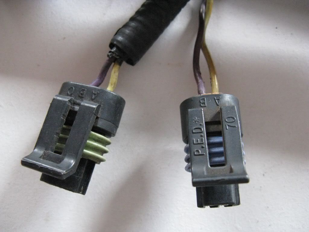
                      The donor harness I used had the wires reversed in the plug. If it is an alternating current signal, it really should not have mattered, but it obviously does. So for those with similar issues, unless the wiring in your harness ends look like the picture, you will have a problem.

                      Thanks again CNCGuy. I am pretty good at swaps and electronics, but this was was bizarre enough that I don't think I'd ever have found it without your suggestion. Who'd have thought about a reversed wire in a 2 pole connector! The 2 prong plug on the donor harness had the purple in "A".

                      Here's how they need to be:

                      Comment


                      • #26
                        As for writing up a guide, please don't do it in a post. I'd much rather have a word document (or something similar) and pics to go along with it, and I will make it into an actual article (most likely on 3x00swap.com). Or, if you want to really do it up right, do it as a PDF that I can just post a link to (I will host it as well) for people to DL and print out.
                        -Brad-
                        89 Mustang : Future 60V6 Power
                        sigpic
                        Follow the build -> http://www.3x00swap.com/index.php?page=mustang-blog

                        Comment


                        • #27
                          kerno: I need to dig up some wiring diagrams, but that is a very good point. And yeah when the voltage is generated by the hall-effect sensor, it can be negative or positive depending on polarity and that is what matters with these PCM's reading it apparently.

                          OT: Brad

                          I may have a more up-to-date version not yet uploaded, but you can throw that up there for now.. It's a WIP that will be finished when I get to the point of tuning the car. Now that I have the orange car, the swap is going into that and the orange car has issues before I can even drive it as it sits. So the guide is on hold for a while. Still, it's got good info that can be used as is. It's just not 100% beginner approved yet.
                          sigpic New 2010 project (click image)
                          1994 3100 BERETTA. 200,000+ miles
                          16.0 1/4 mile when stock. Now ???
                          Original L82 Longblock
                          with LA1, LX9, LX5 parts
                          Manifold-back 2.5" SS Mandrel Exhaust. Hardware is SS too.

                          Comment


                          • #28
                            Awesome, I will add it tonight.

                            UPDATE : Added -> http://www.3x00swap.com/index.php?page=OBD1-5-to-OBD1
                            Last edited by bszopi; 02-24-2010, 09:41 PM.
                            -Brad-
                            89 Mustang : Future 60V6 Power
                            sigpic
                            Follow the build -> http://www.3x00swap.com/index.php?page=mustang-blog

                            Comment


                            • #29
                              Awesome job figuring out! That's what I was trying to say before was checking all the icm connections because when one of mine fried before it created conditions that even confused the dealer.
                              I'm glad too some else has accomplished the LX9 swap!

                              Comment


                              • #30
                                Swaps using the newer engines are becoming more popular. I would estimate there are close to fifty of them as of now. Although most are in FWD cars, I can think of at least six LX9 and three LZ9 powered MGs.
                                MinusOne - 3100 - 4T60E
                                '79 MGB - LZ9 - T5
                                http://www.tcemotorsports.com
                                http://www.britishcarconversions.com/lx9-conversion

                                Comment

                                Working...
                                X