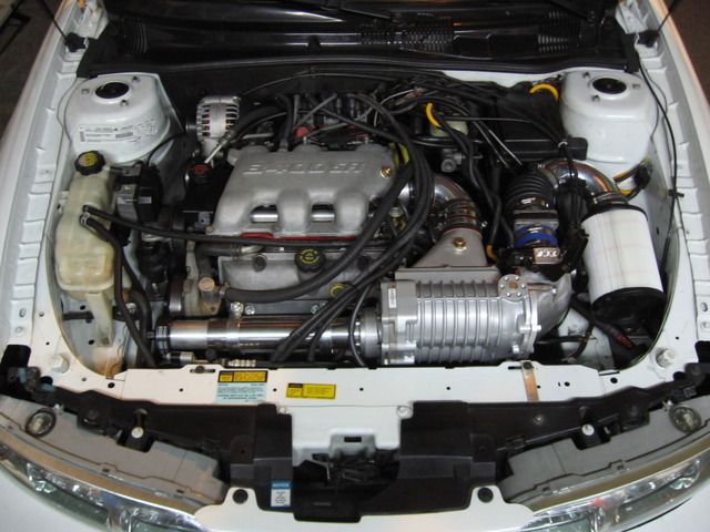
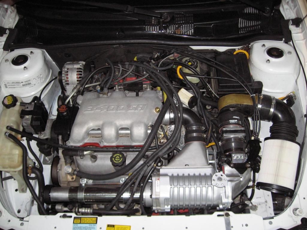
Intercooling efforts are going slower than expected, but meanwhile there are some refinements to report. We got a whole 1/4 inch extra hood clearance, and it has done well for the last few days. I have yet to take a speed bump too fast just to test it, that's not something I'd normally do anyway.  More clearance can be had, but this will probably be enough for me. You can see that the unit is moved slightly down and in, rotated more upward to the rear.
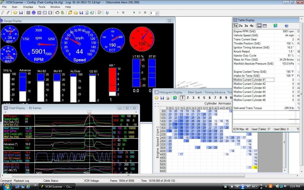
Also went from the 3.0 pulley to a 2.8. Now seeing it peak at 14 psi, with noticably more KR. It's really too cold out now to get any meaningful scans, but the airflow #s are thru the roof even with the Fram paper filter (or who knows maybe because of it lol)
Changed to stock 3.0 idler pulley (edit: after it settled in, had to go to a 3.25 idler) with a 1038K6 belt. Just a bit on the loose side but the 1030K6 belt was too tight. So I could use something in between those. Not that big a deal, just could be better.
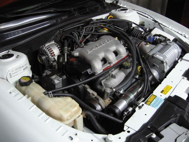
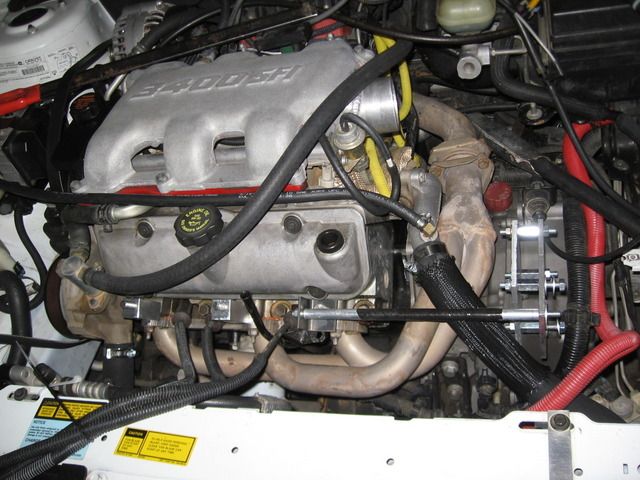
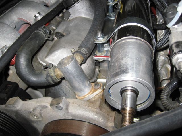
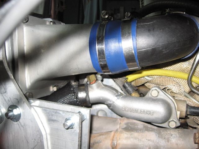
The driveshaft mount starts with two 1 inch square aluminum posts with a 10 mm through-hole in each, offset 1/8 inch from center. They are mounted diagonally on two SS 10mm studs on the engine (not like in the pic ). It was necessary to file the header flanges a little at the top to get a flat surface. Height is adjusted by changing the post size. Then shims are added or removed on the cross brace tube mount, and the mounting plate holes redone (new plate must be made for each change). I'll fill in the dimensions and add pics as time allows.
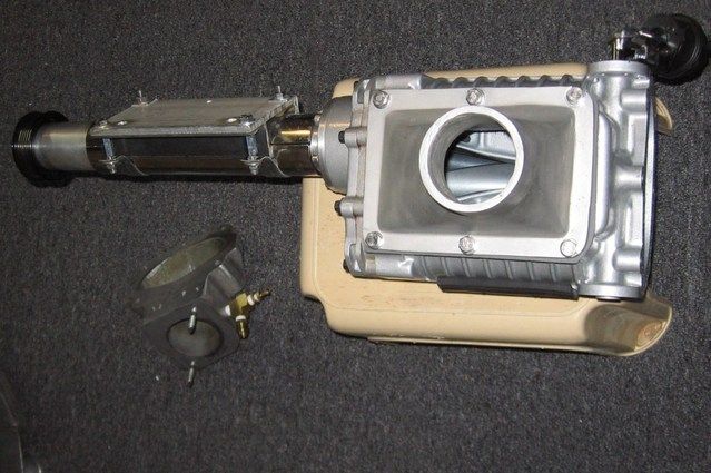
 More clearance can be had, but this will probably be enough for me. You can see that the unit is moved slightly down and in, rotated more upward to the rear.
Also went from the 3.0 pulley to a 2.8. Now seeing it peak at 14 psi, with noticably more KR. It's really too cold out now to get any meaningful scans, but the airflow #s are thru the roof even with the Fram paper filter (or who knows maybe because of it lol)
Changed to stock 3.0 idler pulley (edit: after it settled in, had to go to a 3.25 idler) with a 1038K6 belt. Just a bit on the loose side but the 1030K6 belt was too tight. So I could use something in between those. Not that big a deal, just could be better.

The driveshaft mount starts with two 1 inch square aluminum posts with a 10 mm through-hole in each, offset 1/8 inch from center. They are mounted diagonally on two SS 10mm studs on the engine (not like in the pic
 ). It was necessary to file the header flanges a little at the top to get a flat surface. Height is adjusted by changing the post size. Then shims are added or removed on the cross brace tube mount, and the mounting plate holes redone (new plate must be made for each change). I'll fill in the dimensions and add pics as time allows.



Comment