I was kind of surprised with the extensive following of the TGP no one has posted a how to rebuild your own T25? Well those of you who want to learn read on, it will save you lots of money and you will know it was done right! I took a lot of what I did from a how to rebuild a T25 for a saab 9-3 the link is here for more information: http://photo.platonoff.com/Auto/2005...Turbo_Rebuild/
Lets get started:
First thing get yourself some tools and lubricants, for this project you are going to need:
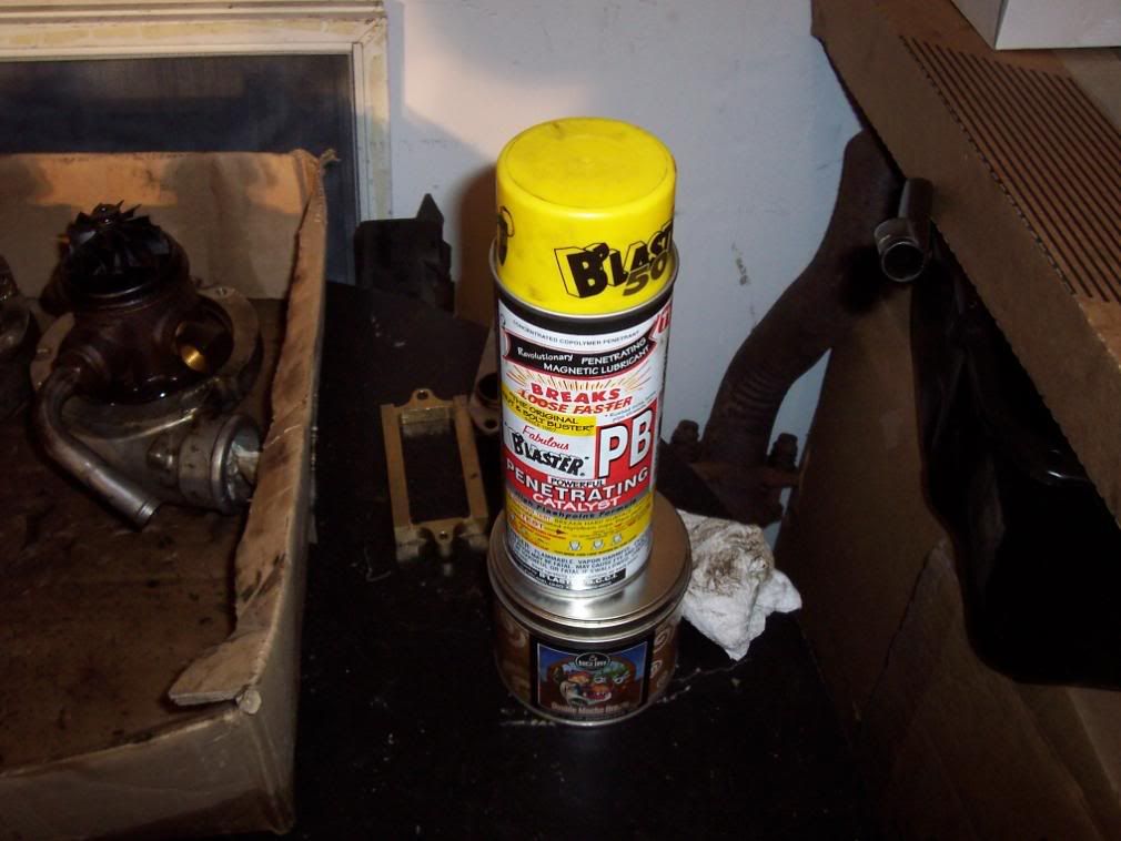
-PB Blaster and lots of it
-A Clean Working Station
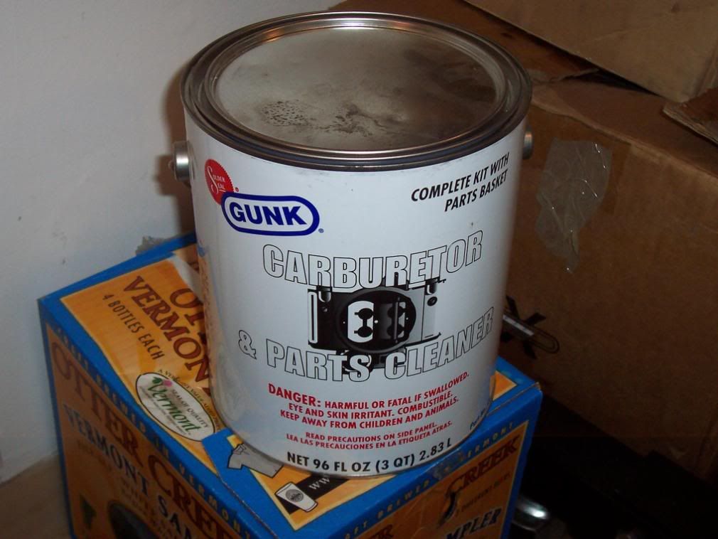
-1 Gallon Bucket of Chem Dip or Gunk Engine Parts Cleaner
-1 Quart of 30 weight oil
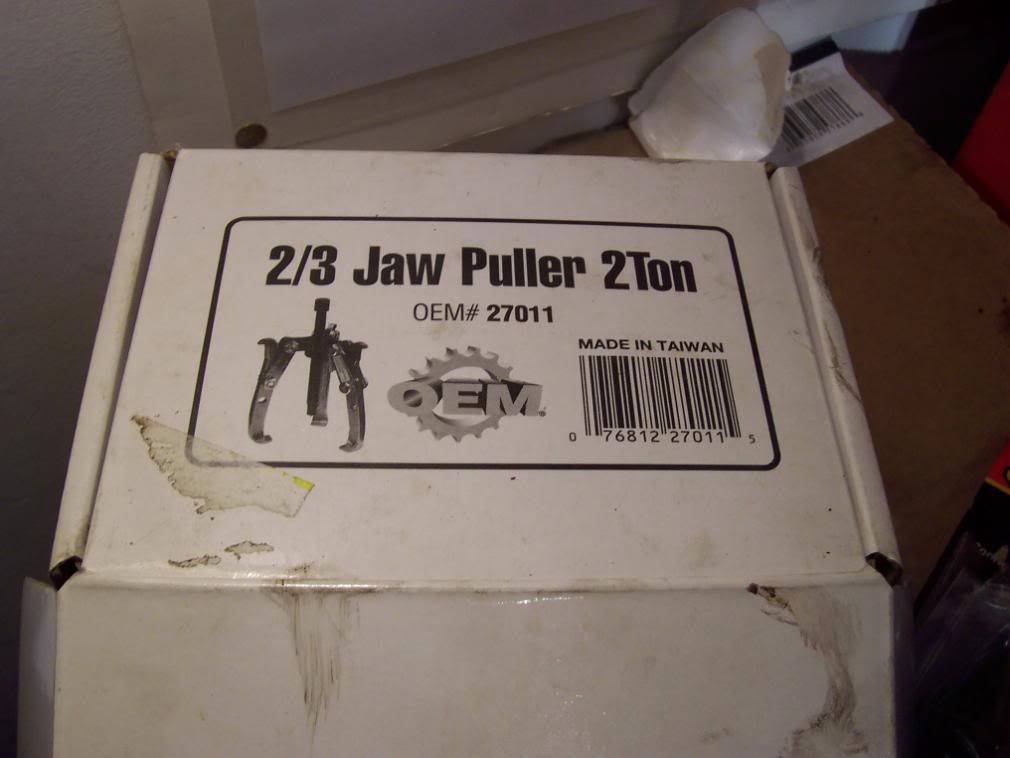
-Mini 3 Jaw Puller (I rented from Autozone see picture for p/n)
-A Large set of Internal Snap Ring Pliers (I got lucky and maintenance at work had a pair, otherwise plan on spending $120 or hunting for a pair in your local wrench heads toolbox)
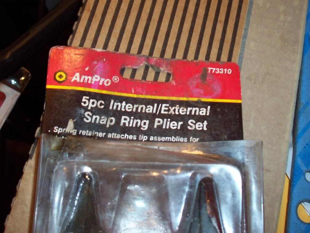
-A Small set of Internal Snap Ring Pliers
-Hammer
-Various small and large flat head screwdrivers
-13 mm wrench
-12 mm wrench
-10 mm wrench
-Standard 12 point sockets and ratchet
-T15 Torx bit
-Carb Cleaner in a spray can
-1200 F ceramic spray paint
-Ebay T25 Turbo Rebuild kit (I got mine for $58 plus shipping)
-Awl or drift pin
-Paint Pen or Grease Pencil
-Wire Brush
-Paper Towels
-Time, this being my first time it took me roughly 6 hours to do this including time to let stuff soak in the chem dip
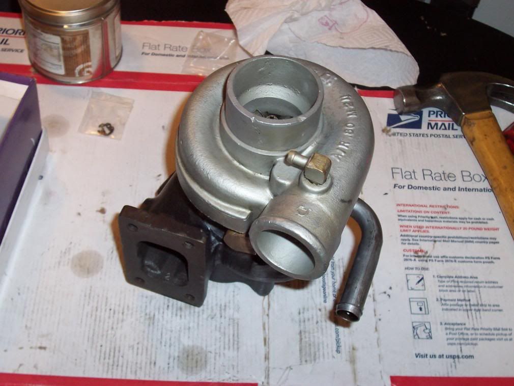
First thing, flip the turbo onto it's turbine housing and mark the relation of the turbine housing to the CBH (Center Bearing Housing). Do the same for the Compressor housing. Use the drift pin and hammer to make "dots" on each. You do not want to get this wrong when you re-assemble.
Next, soak the turbine housing (exhaust side) with PB blaster (The BEST!) around the bolts and where the metal spanner clamps are. I did this step before I actually planned on taking the turbo apart so mine was soaking for about 2 weeks, on and off as I walked by I sprayed it. If you got the time this is the safest way to make sure you don't shear any bolts in the housing.
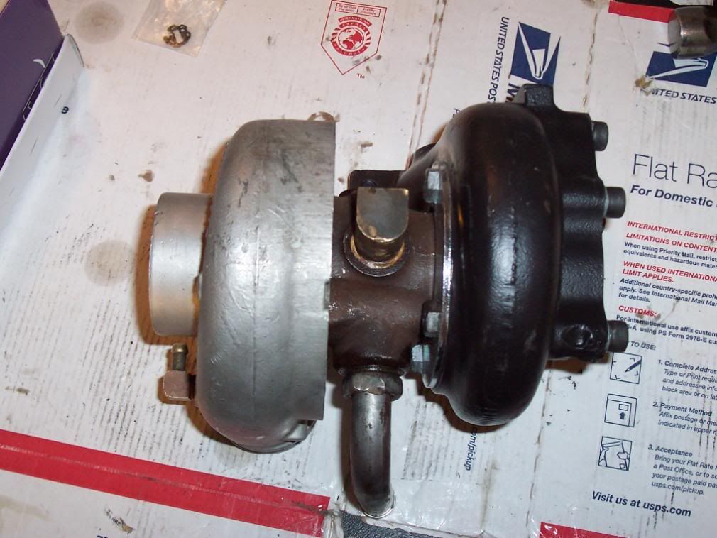
Remove the 4 bolts and spanner clamps from the turbine housing. Your housing may or may not drop off the CBH. One my turbos did the other I had to motivate with a hammer. When you are wailing on this thing to get it out try to strike it all around not just one side otherwise it will bind up and you will get nowhere.
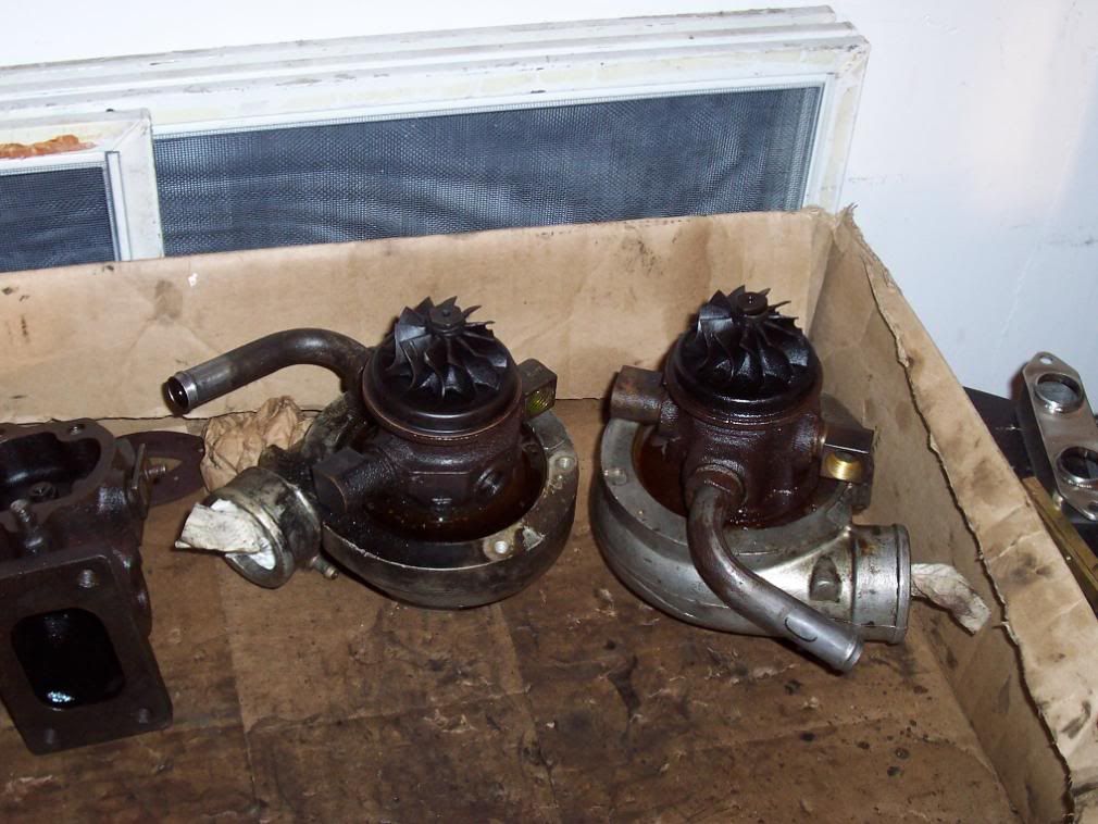
Being an mechanical engineer by day I have access to all kinds of goodies at work such as a particle blaster and machine shop. Thus it was no question that I took the turbine housing to work and bead blasted it as well as used a government favor to have one of the broken off studs on the downpipe flange machined out and tapped. They even gave me some nice grade 8 socket head cap screws (SHCS) for the project. You may not have access to a bead blaster or machine shop but I'm sure it would not cost all that much to have the local engine shop blast it for you or take out a bolt. Otherwise just soak it in the chem dip for a while and wire brush the housing, it's going to rust later anyways
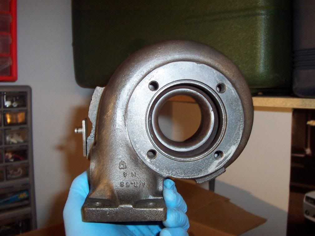
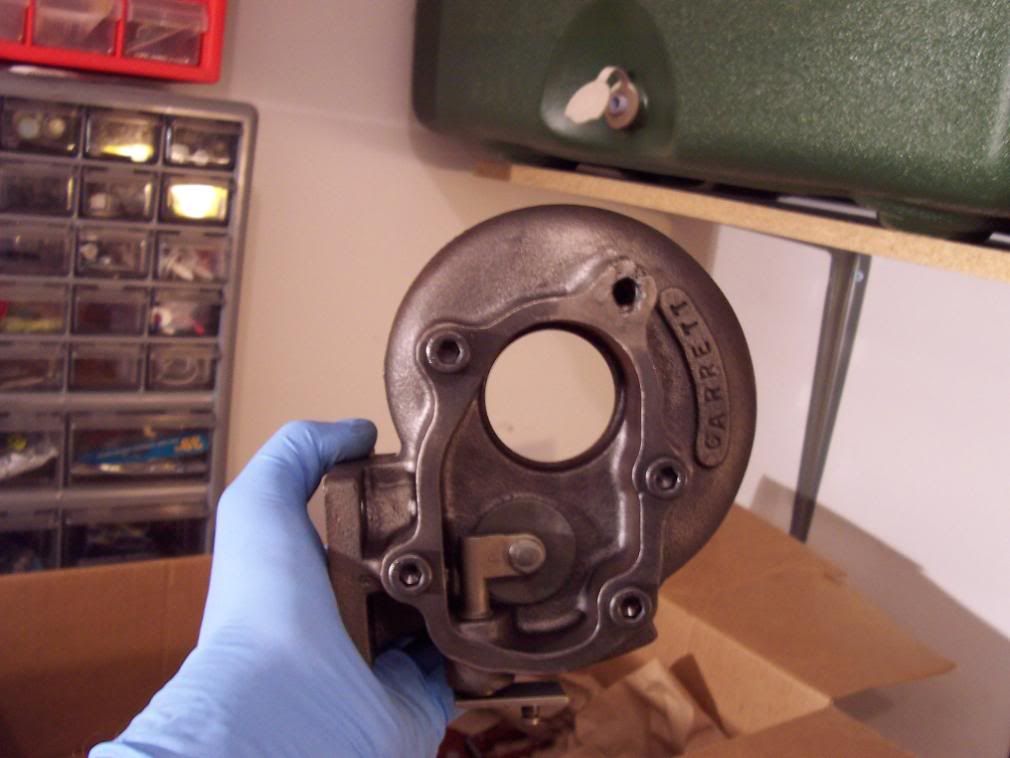
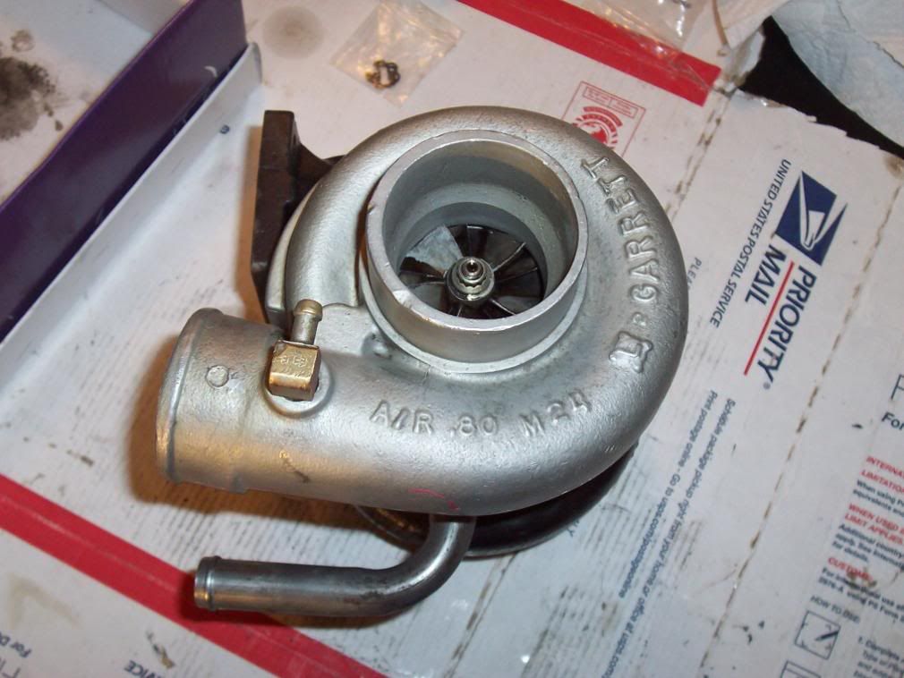
Now put the turbo on it's compressor housing and soak the big snap ring/housing with PB Blaster. Let it soak for a while. Now prop it on it's side being EXTREMELY careful NOT to put ANY LOAD ON THE TURBINE BLADES!!!!! I cannot stress this enough you will hate yourself if you bend any of those things. Now get a big flat head and a hammer and beat the piss out of that snap ring until it moves around. I hit it on the ends trying to push them closer together. Once you get them moving a bit get the big pair of internal snap ring pliers with the correct tips and begin to compress that snap ring. When you can see the edge of it get a buddy or if you do yoga grab a medium flat head and pop the side of the snap ring out that you can get at. Don't worry about it amputating your arm as the CBH will keep it from ninja staring into the wall.
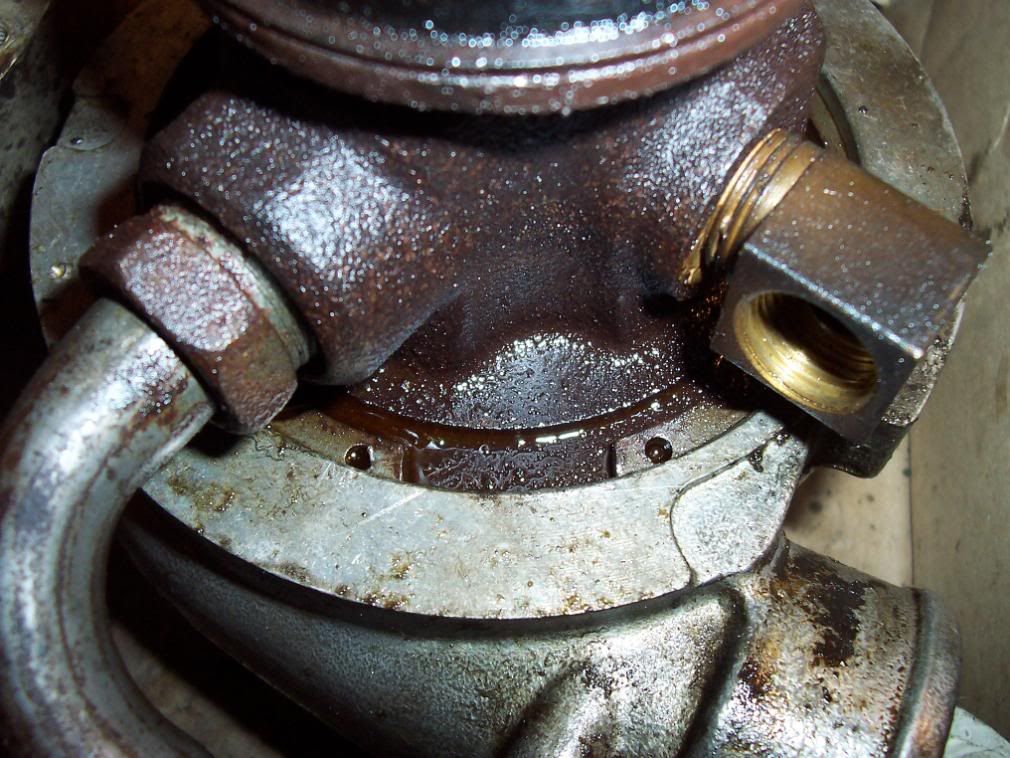
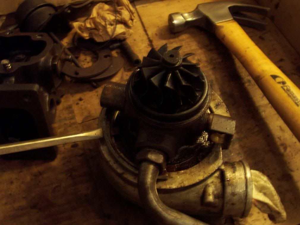
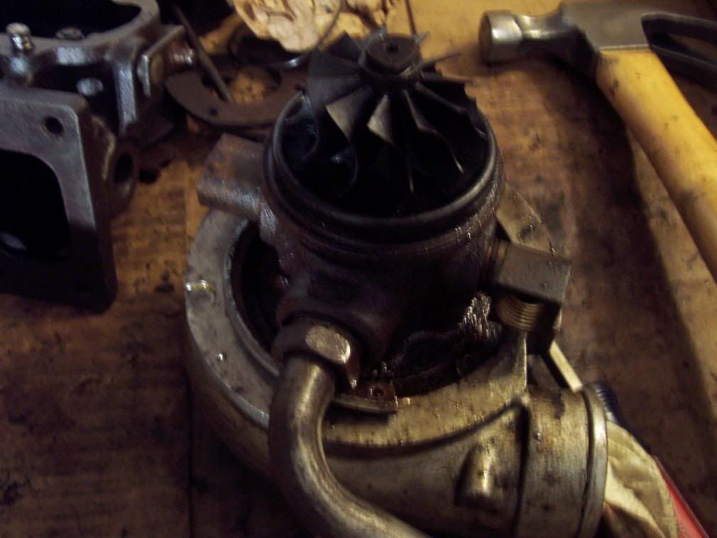
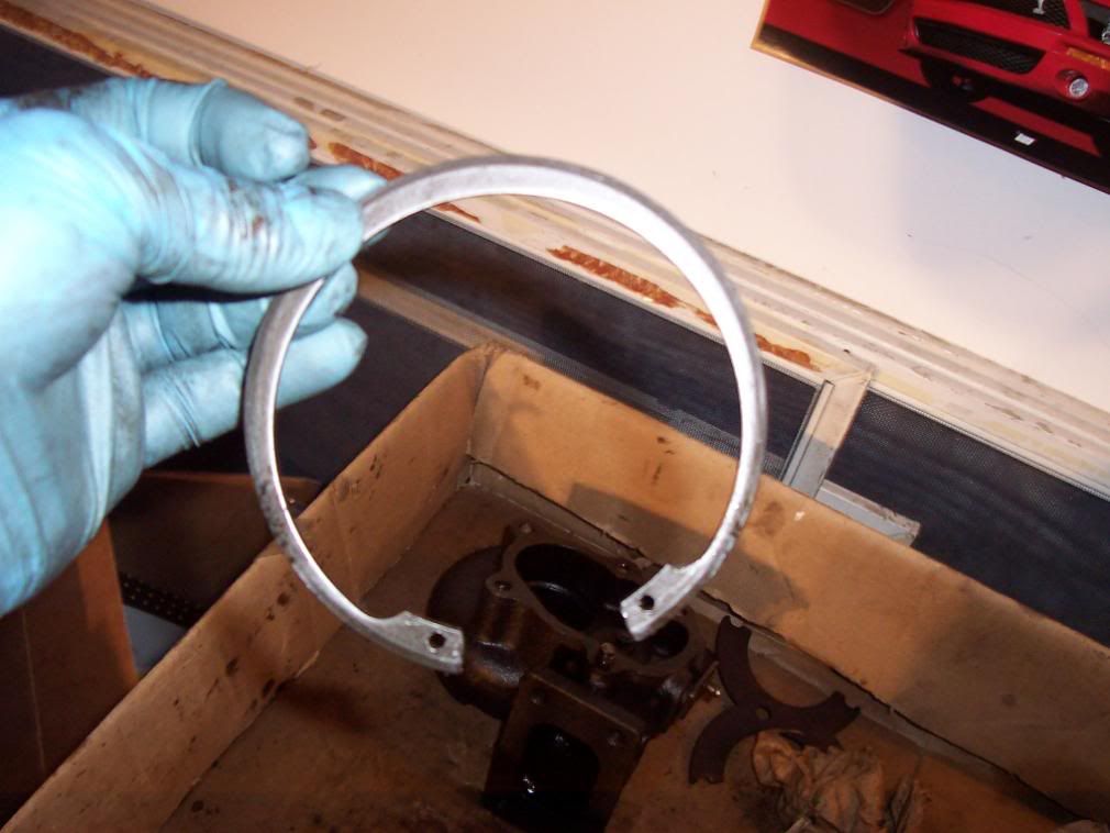
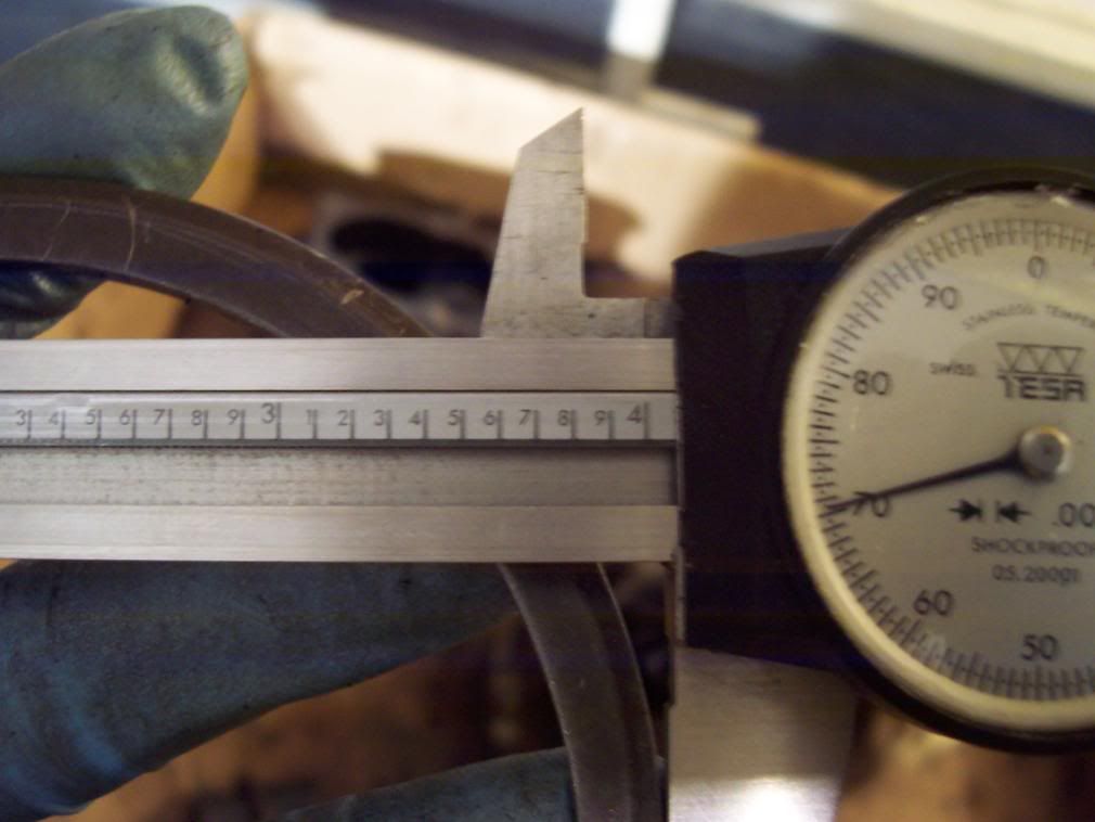
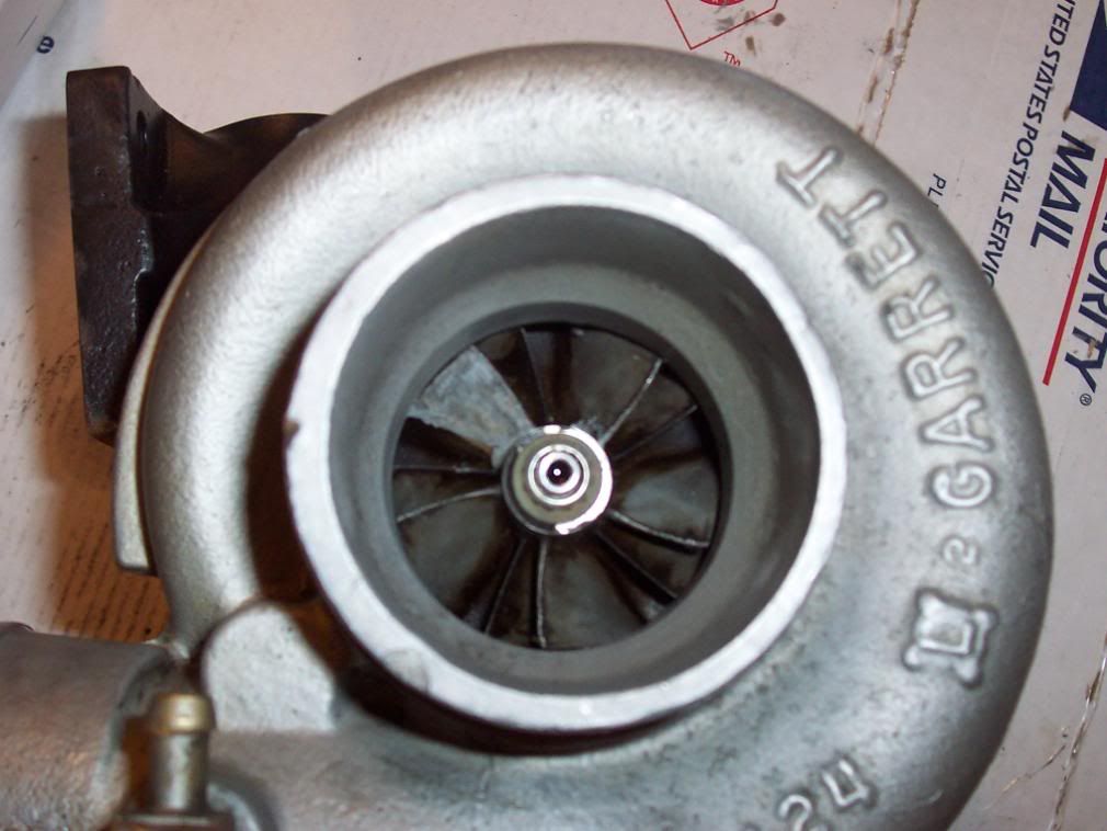
So now you got the compressor housing off, these two steps are by far the hardest and from here on in it is pretty simple and straight forward provided your guts of the turbo are good. Take the old O-Ring out of the housing. Take the compressor housing and dump it into the chem dip. Now inspect the vanes of the turbo, note any bent or worn areas. If you see anything like this I would recommend you stop and get new compressor or turbine vanes. These things are balanced much like your engine and if something is bent, worn or missing outright it will not perform properly in operation, could hit some nasty resonance during operation or hit the housing and throw chunks of metal into your engine. In any case the car will not be fast and could end up costing your a lot more money than the vanes cost so if it looks bad replace it.
I had two turbos the first one had a bent turbine vane so I opened the other turbo up and used it’s vanes and shafts.
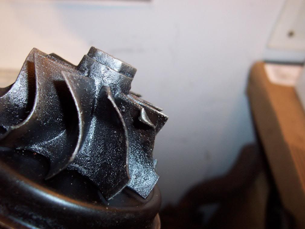
At this point if everything looks good we are going to take the turbo apart. Before you do this make sure to mark the relation of the turbine vane to the compressor vane. This will allow you to maintain the balance of the turbo (and save you $$). After you mark it make sure to take a picture or make a sketch to make sure you put it back as close as possible. I used the tip of the compressor vane lined up to the left tip of the turbine vane. Point is find some identifying feature to line it up against, if you want you could always mark the vanes to each other and the vanes to the housing to get it dead on. I did not think of this until after I took mine apart, oh well.
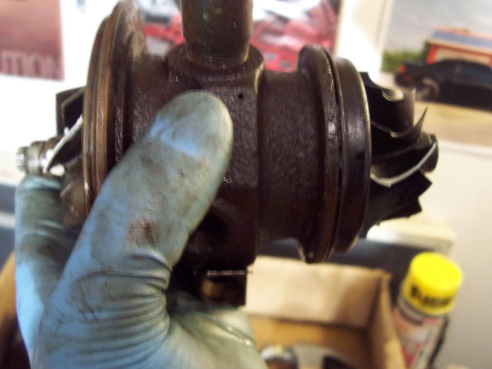
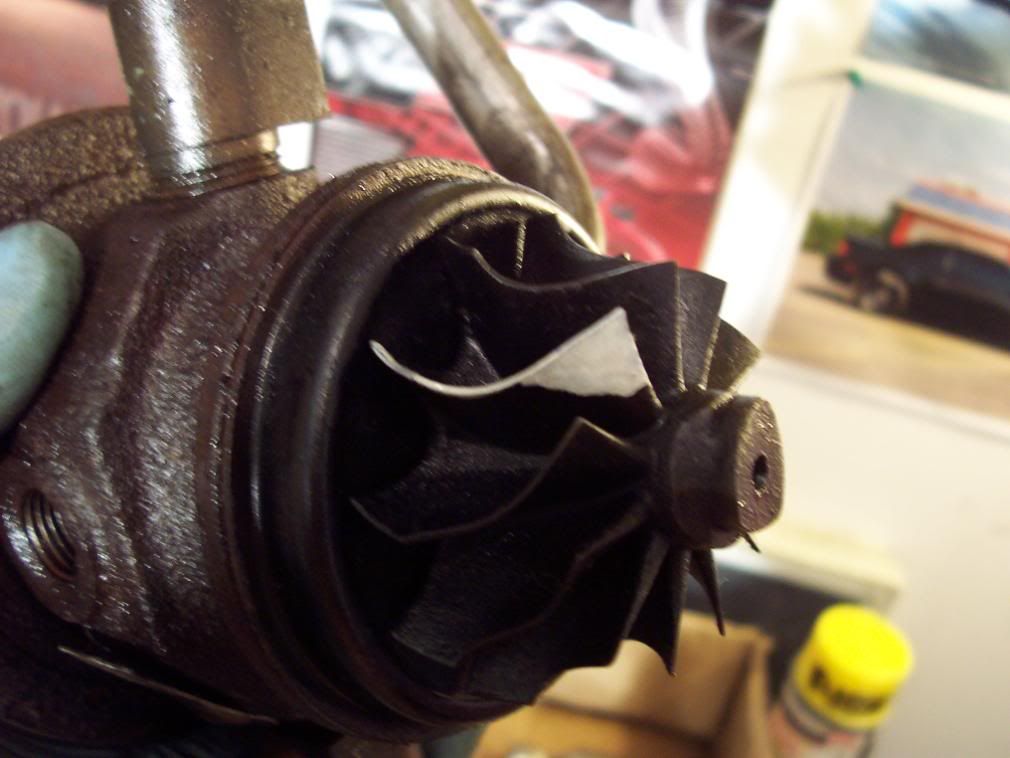
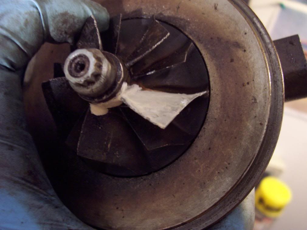
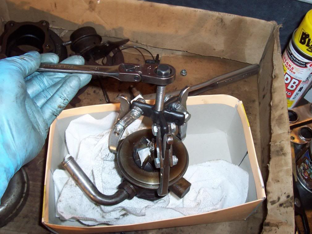
Now we are ready to unbolt the shaft. Remember the nut on the compressor end is left hand threads this means it loosens by turning to the right not like all other threads on this thing. If you don’t understand what I’m saying you best not be trying to rebuild your own turbo. Take a 12 mm open end wrench and hold the turbine end and use a 12 point socket with ratchet on the compressor side. These sizes will vary, I think my compressor end was a standard socket but I forget which size. Hold the turbine end with the open end of the wrench and turn the ratchet to the right! It should crack pretty easy and you can thread the nut off.
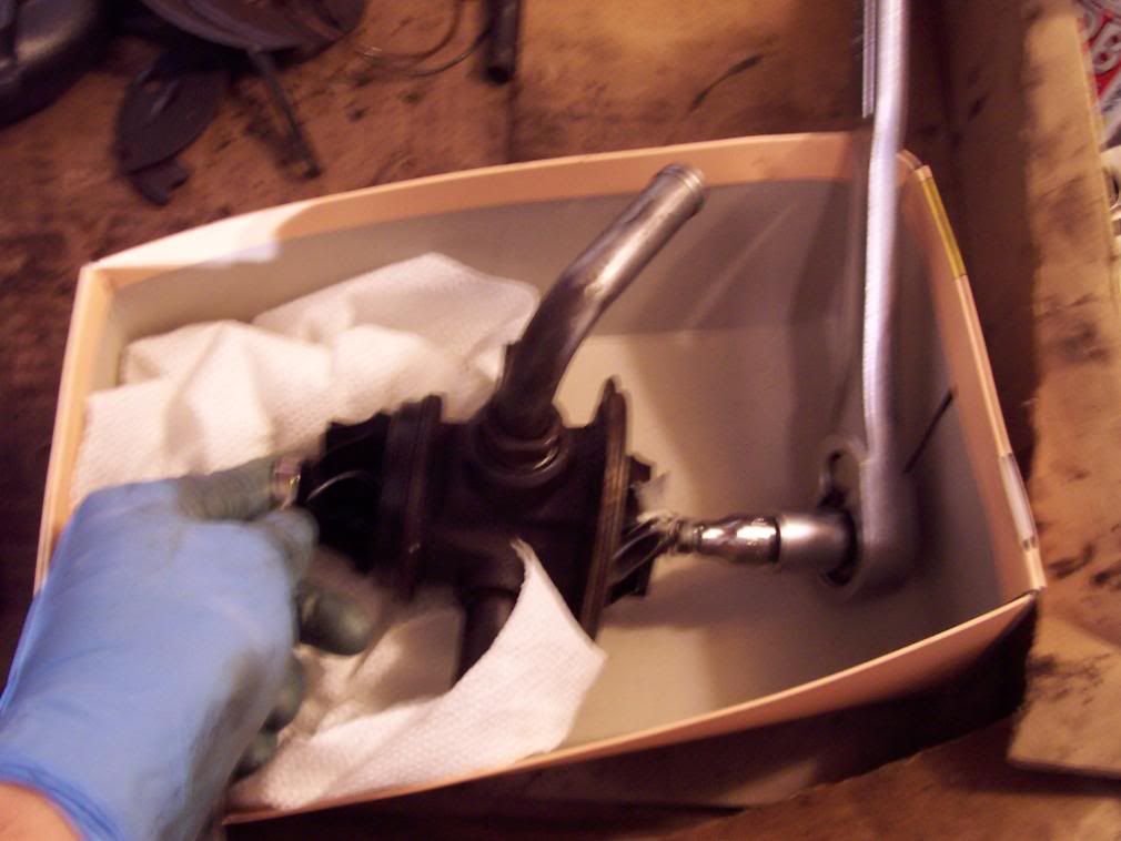
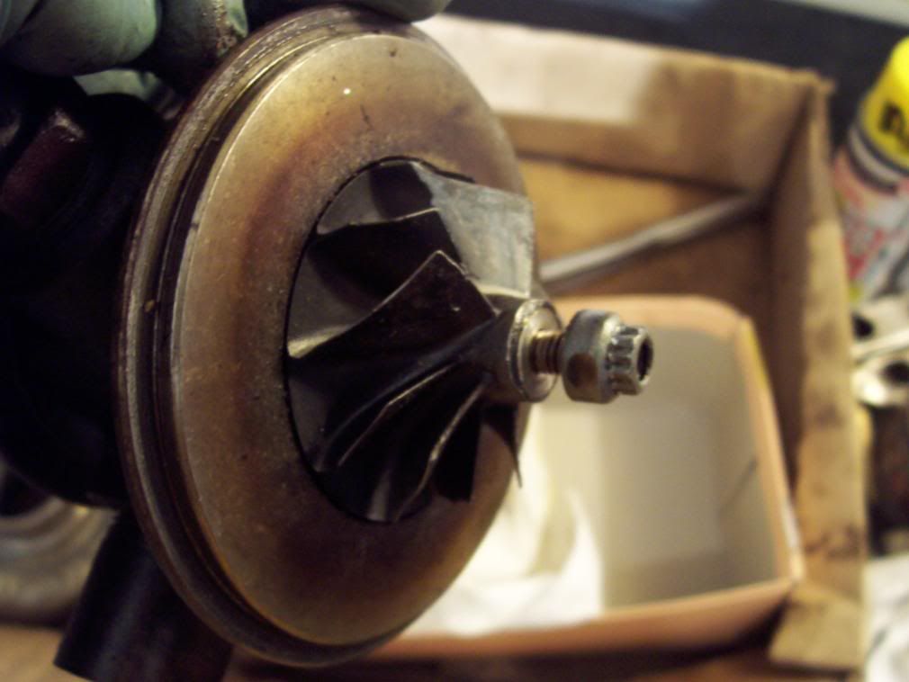
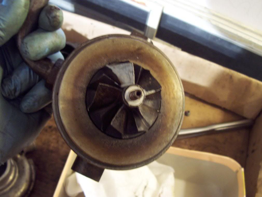
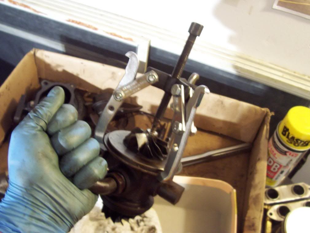
Ok get your autozone 3 jaw puller you rented and put the jaws on the flange on the compressor end of the CBH and tighten the shaft until it pilots onto the dimple in the compressor end of the shaft. Now take a 13mm wrench or socket and turn the thread on the puller until the shaft is pressed out of the housing. BE CAFEFUL the shaft and turbine will drop out, have a towel or rags in a box for it to drop into. Again you don’t want to bend those vanes.
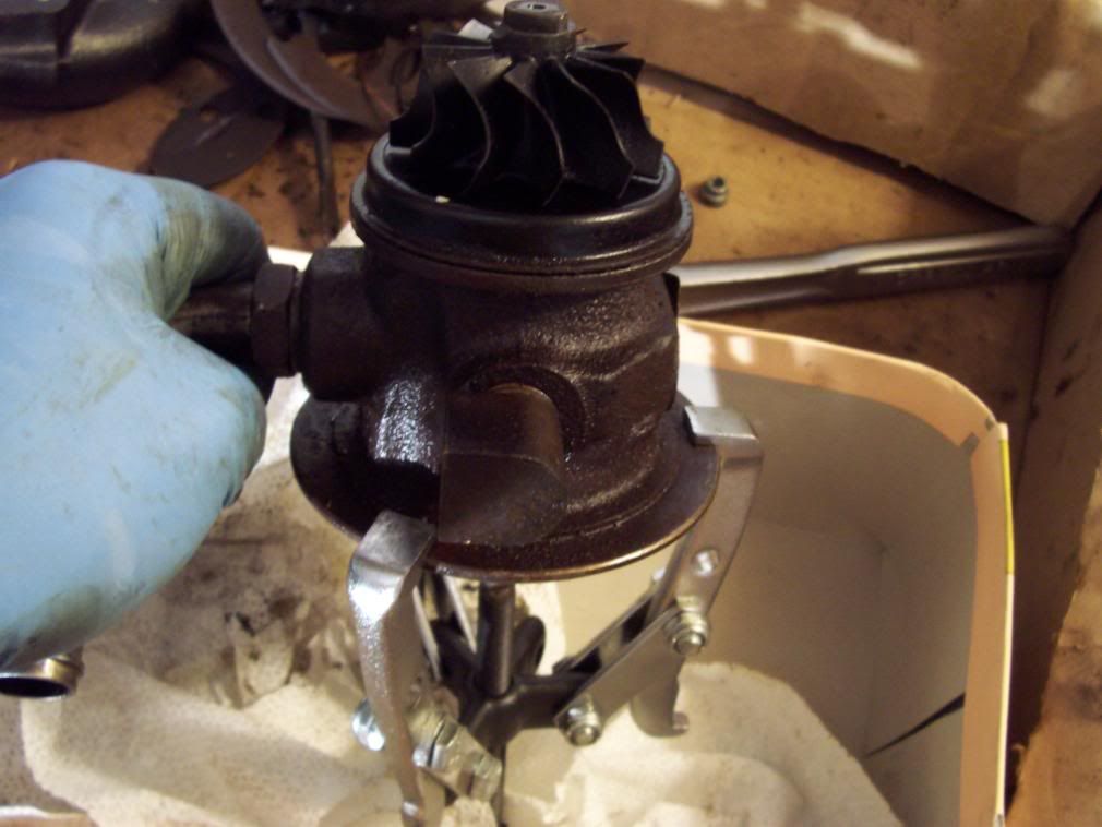
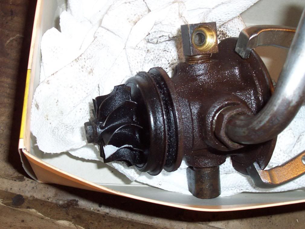
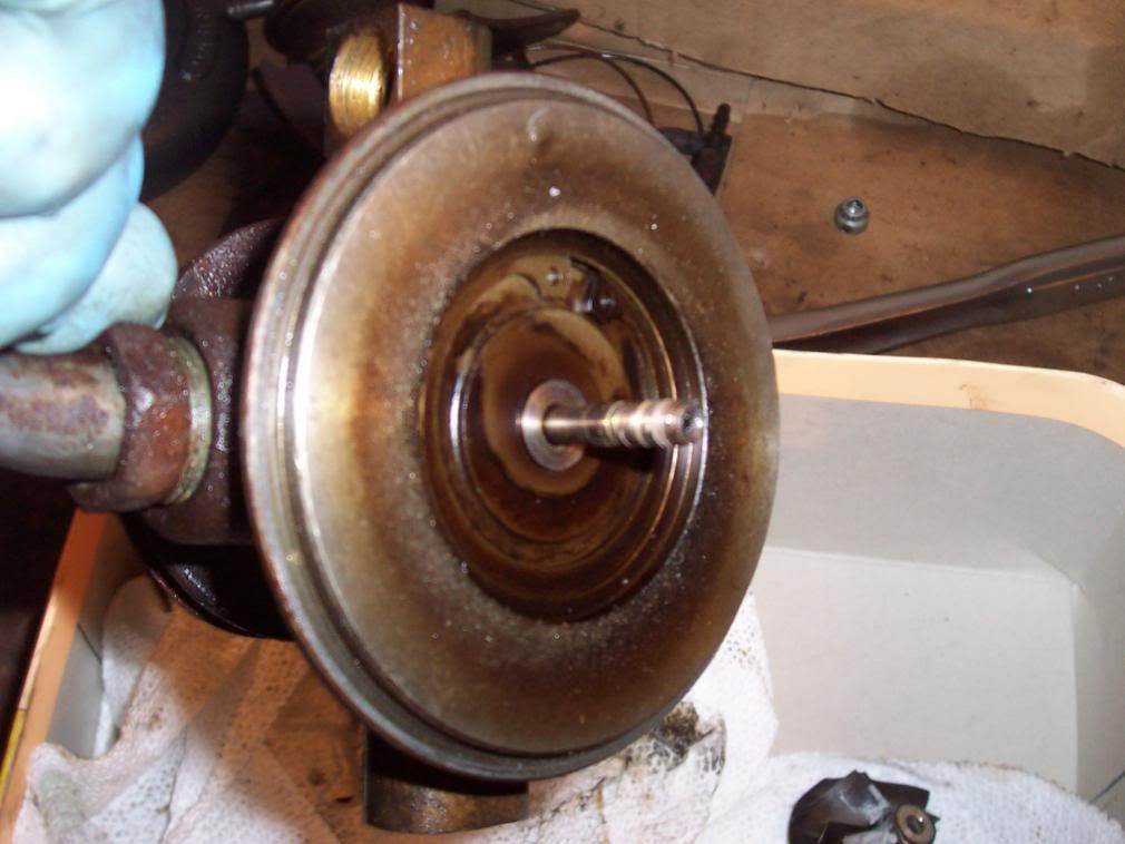
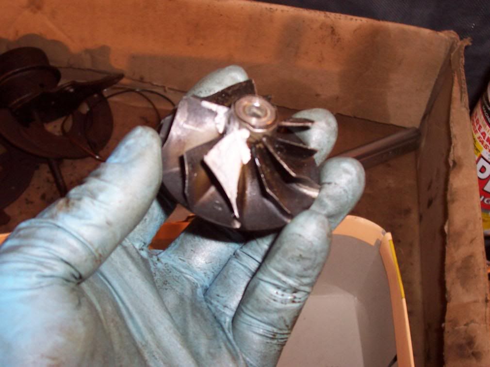
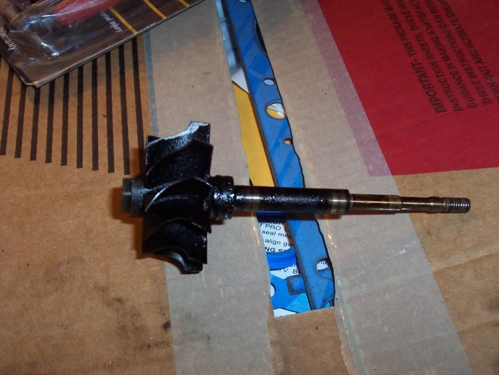
Don’t be a wise guy and soak them with carb cleaner to make them look pretty you will dissolve your markings. If you have to clean the vanes use a paper towel with some chem. Dip on it and carefully wipe them individually skipping the painted vanes. Take a minute and inspect the shaft for any abnormal wear on the bearing surfaces. This would include deep grooves and excessive scratches. It should be a smooth surface. Discoloration is fine as long as it is smooth. If it is really dirty like mine was take some chem dip on a paper towel and wipe down the shaft and buff it by hand with a copper wire brush to get stock on carbon off. There is a compression clip on the turbine end of the shaft, take this off with a small screwdriver and clean out the groove. Put in a new compression clip and put the shaft and vanes off to the side. Take the turbine cover plate and clean it up in the chem dip.
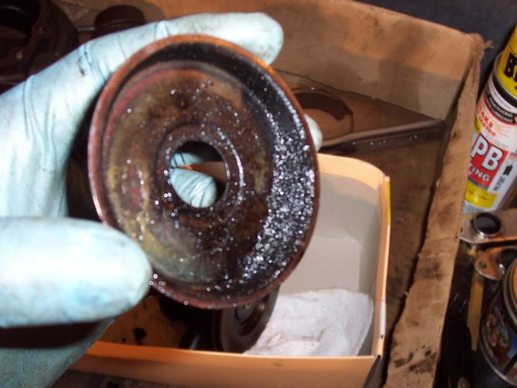
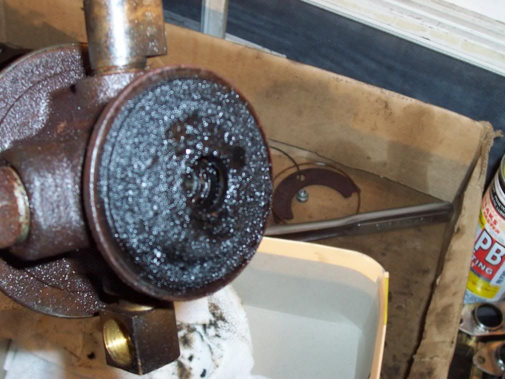
Now take your set of small snap ring pliers and take the snap ring off the seal plate. Using a small flat head screwdriver pry the seal plate off of the thrust bearing. The seal plate is held in with a compression clip and may take some prying around the circumference to get free. Now get a T15 torxs bit and remove the two bolts holding the thrust bearing plate in. Remove the thrust bearing. Check the thrust bearing for excessive thrust clearance and check the surfaces for excessive wear. You may be able to reuse this at a late date if it is not worn out so save it.
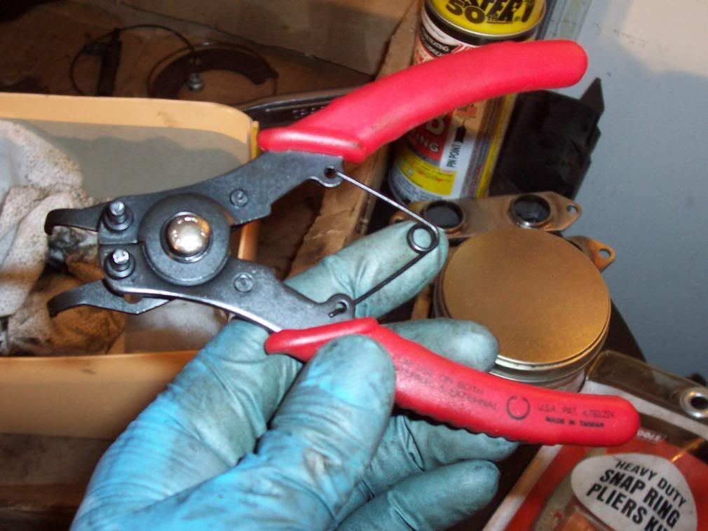
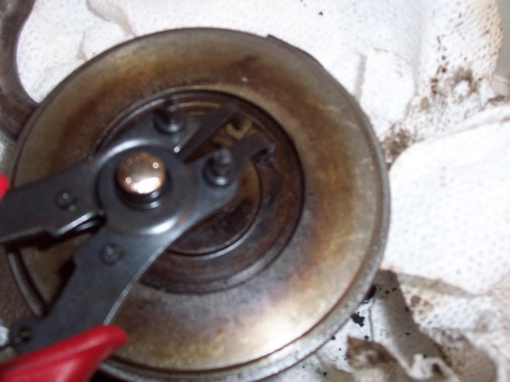
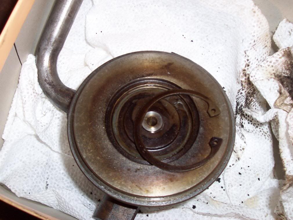
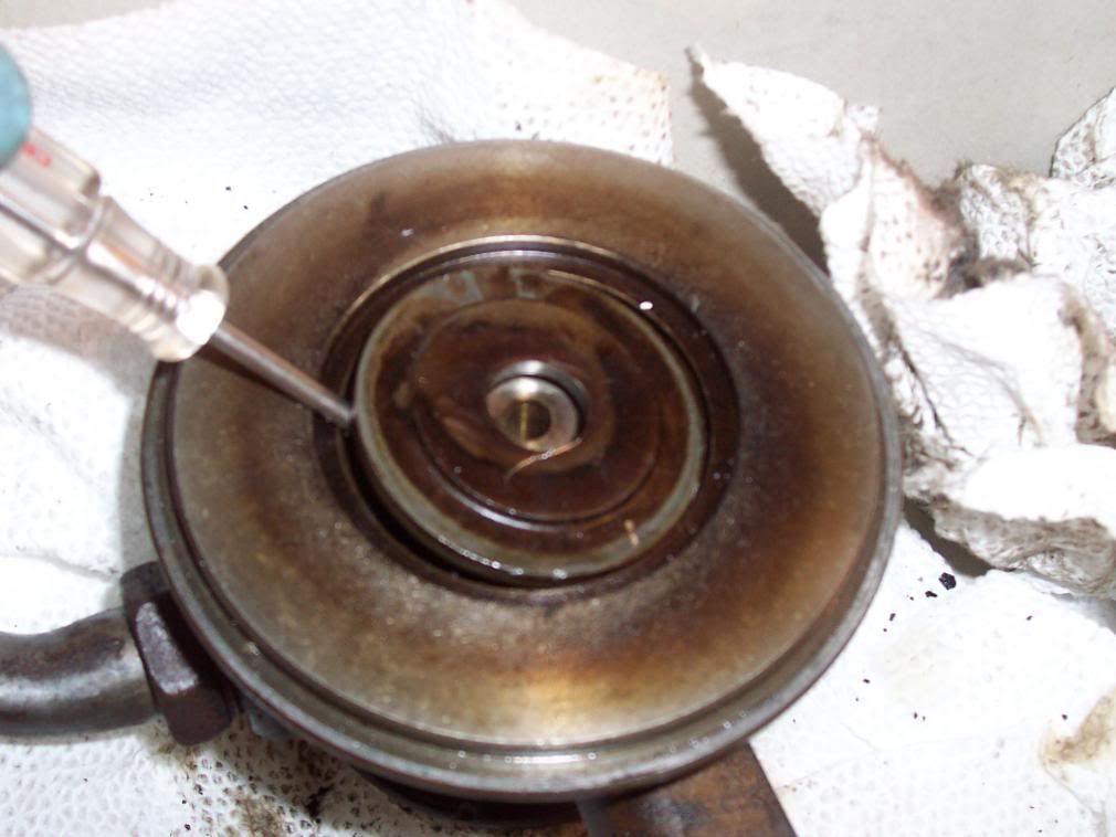
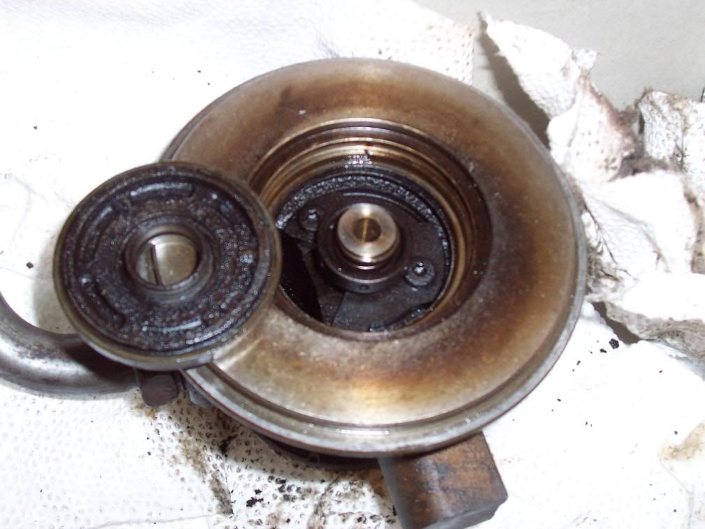
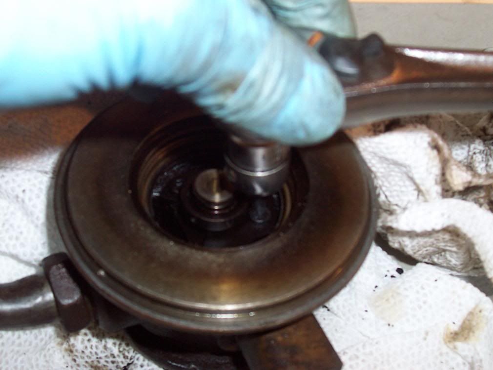
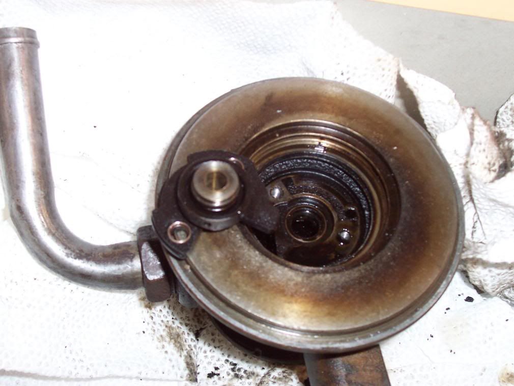
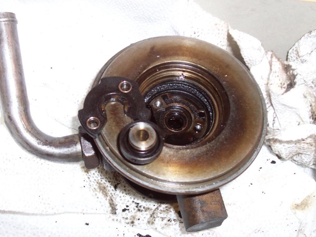
Remove the compressor radial bearing by using a small flat head screwdriver to pop it out by pulling it up on the inner diameter
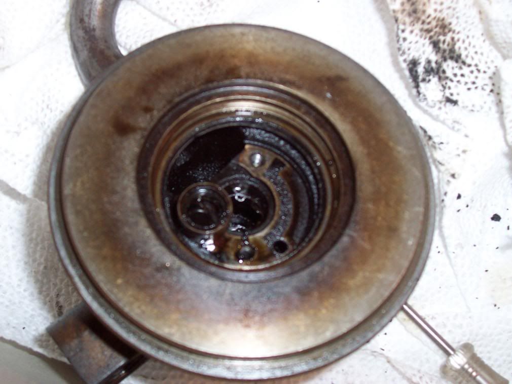
Use a small flat head screwdriver to pry out the snap ring holding in the radial bearing on the turbine side. Remove the radial bearing. Inspect all bearings for abnormal wear on the ID (inner diameter) and OD (outer diameter). Normal wear would be for a polished silver surface on the ID. Abnormal could be a silver surface on only one side, this is called taper and could mean there is a problem with the CBH. Make sure the OD is not worn down too much such as the surface is silver instead of gold. This means the bearing was spinning in the housing instead of the shaft spinning inside of it’s ID. If the OD is all silver like the ID, then you should take your CBH to get measured to make sure the radial clearance is right when you put in the new bearings. Per flybynite: 003-.0035 of an inch clearance on the o.d. and .0012-.0016 of an inch on the i.d. it the proper clearance.
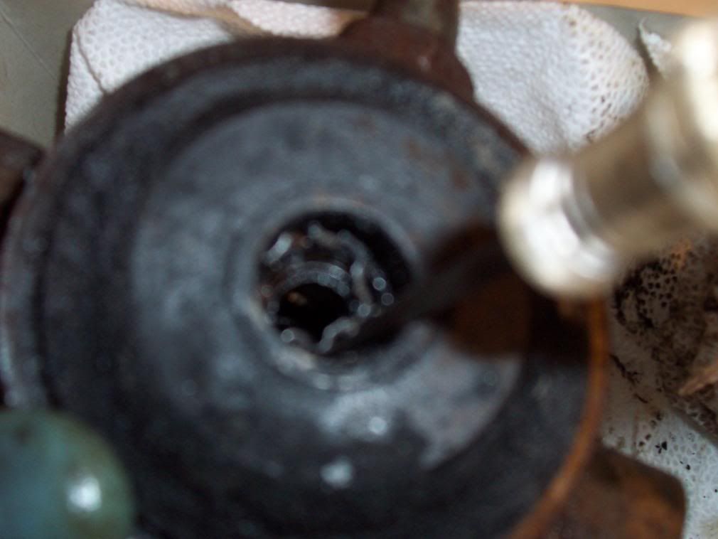
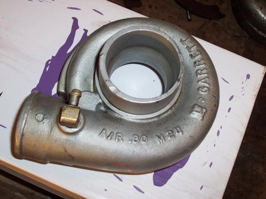
At this time take out the compressor housing from the chem dip and clean it off with some paper towels.
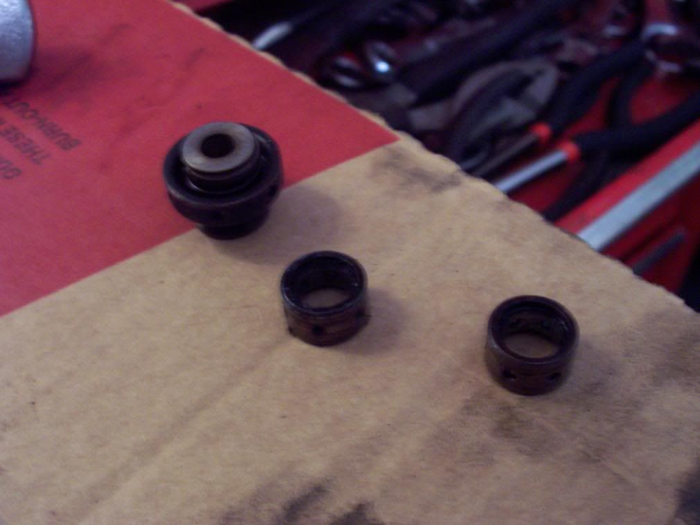
Ok now dump the entire CBH into the chem dip. Let it soak for at least 1 hour and wire brush it and soak it again for 20 minutes min. Take it out and flush it with carb cleaner inside and out to get all the chem dip out and carbon debris. Make sure the bearing surfaces are especially clean and dry. Make sure the oiling holes are cleaned out and not all clogged up with carbon. Now that everything is clean take one of radial bearings and dip it in the 30 weight oil. Drop it into the compressor side of the housing. Now take your new thrust bearing and install the new compression ring supplied. Take the thrust bearing assembly and plate and coat the thrust bearing surfaces with 30 weight oil. Assemble the two. Now take the new seal plate and pop it onto the OD of the thrust bearing where the compression clip is. Make sure the thrust bearing rotates freely in the seal plate. If it does not remove it and reuse your old seal plate. I found my new seal plate did not line up right and had to reuse the old one. Now disassemble the seal plate from the thrust bearing, that was just practice because if it does not line up right after you have the thrust bearing torqued it…you will have to drill out the seal plate if it binds up (speaking 1st hand on this one) and redo all the cleaning and assembly again. Line up the thrust bearing assembly and screw them down. Make sure they are tight. Next take a new O-ring and lay it into the groove in the CBH. Take the new seal plate and pop it into the thrust bearing OD like before. Again make sure the seal plate and thrust bearing can rotate with respect to one another. Secure the seal plate with the snap ring.
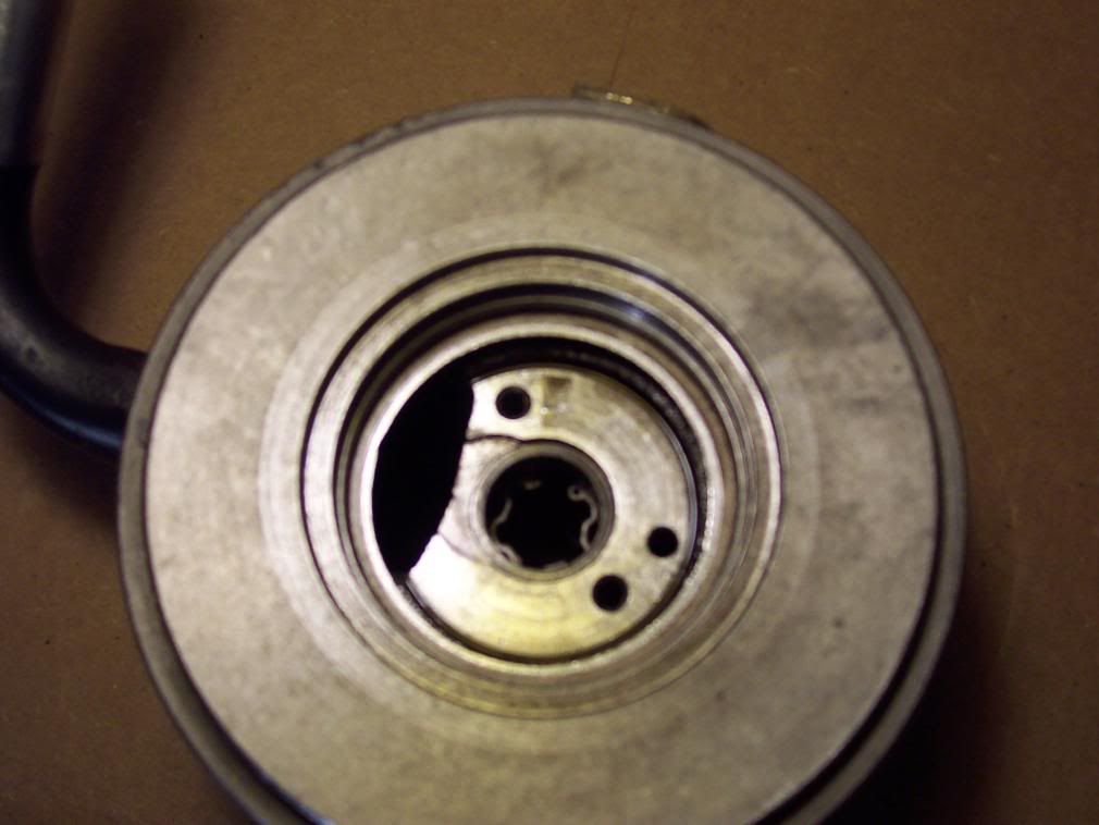
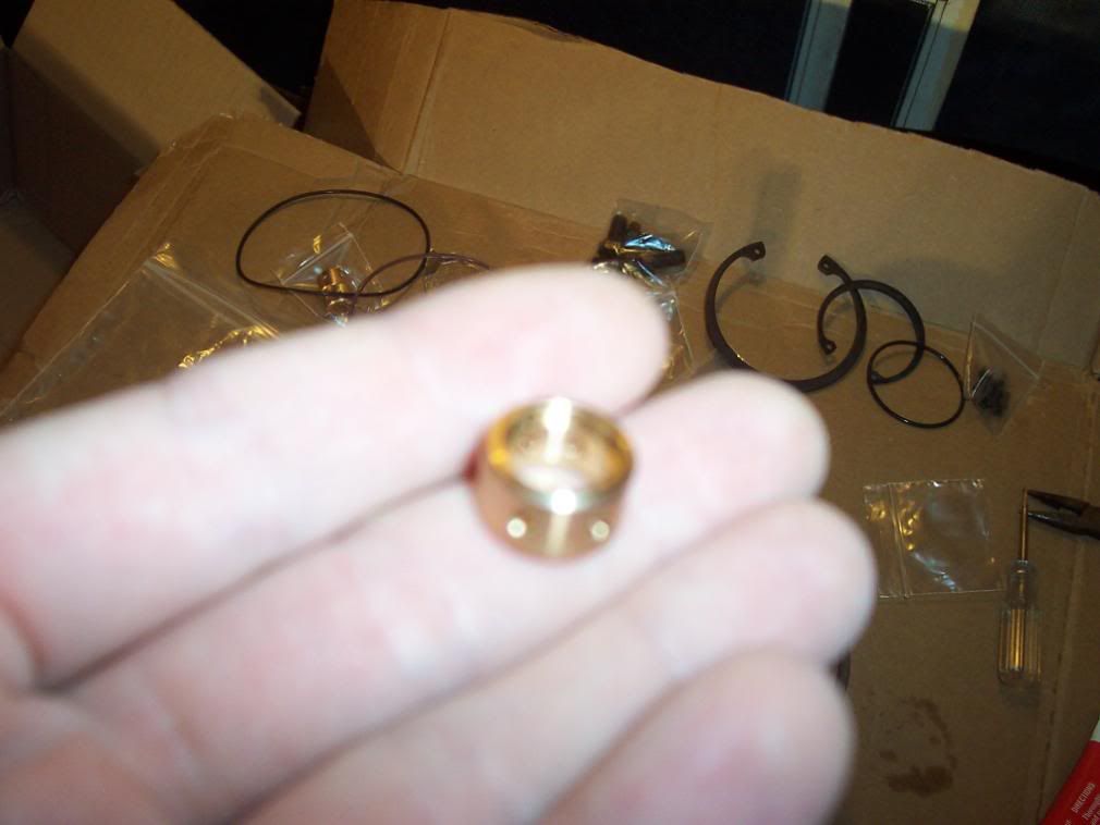
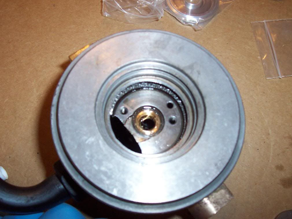
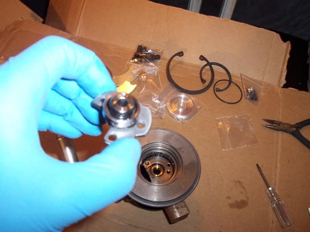
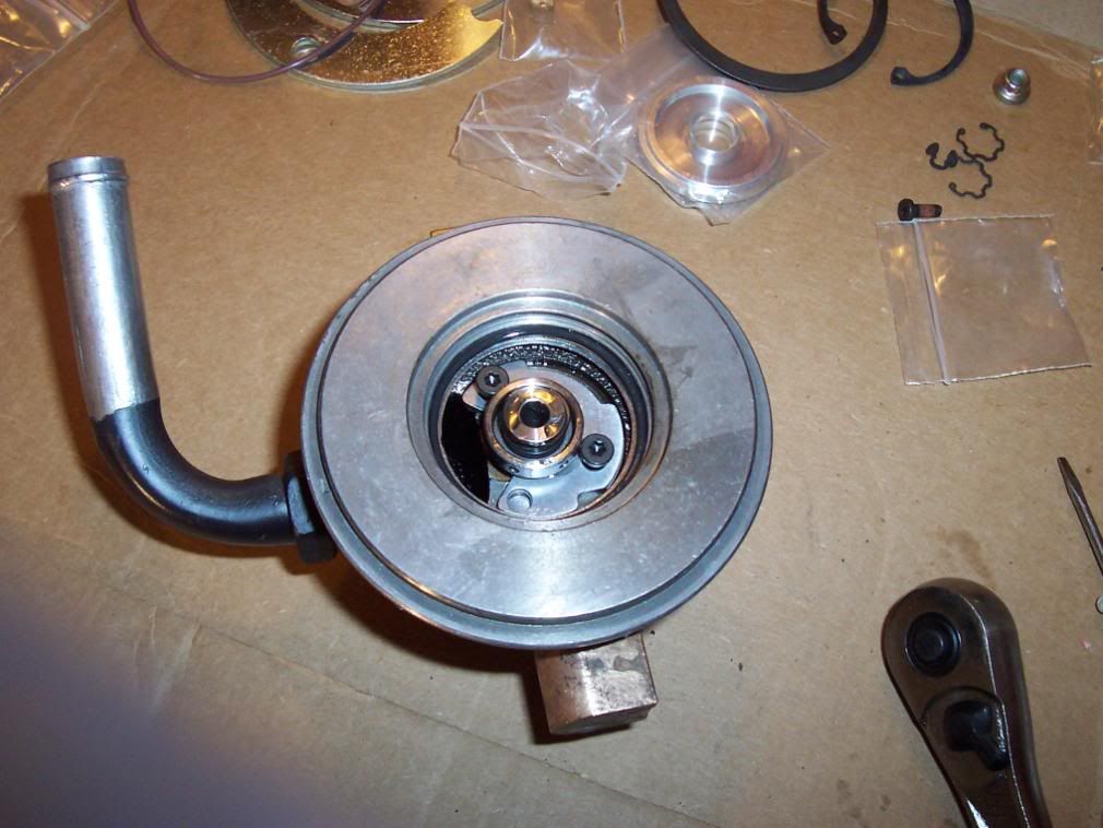
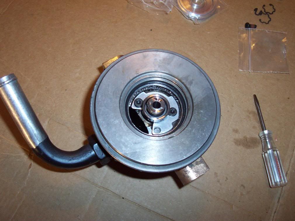
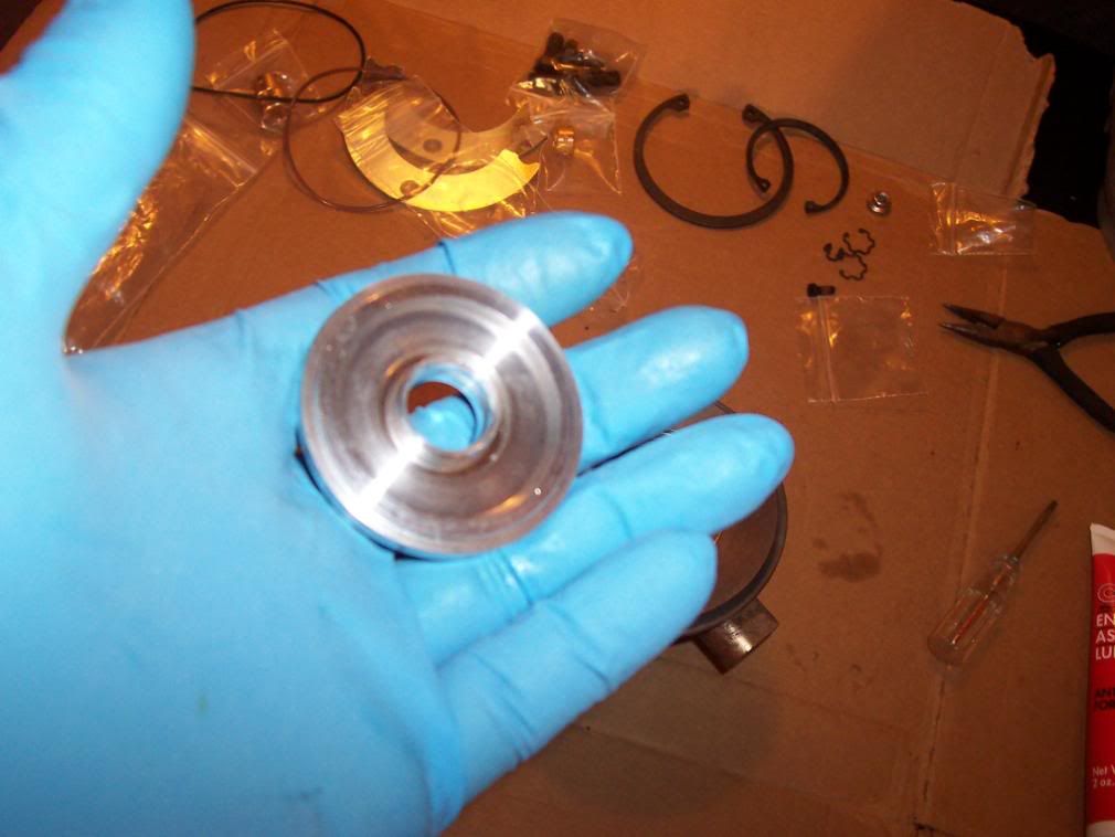

Flip the CBH over and install the new turbine radial bearing. I also forgot to mention if you like you can replace the inner snap rings in the CBH with new one supplied in the kit. Mine were seated nice and showed no wear so I left them in there to make life simple. Secure the turbine radial bearing with a new snap ring. Make sure it is seated in the groove properly by pushing on it with a flat head to see if it pops out and shoots across the room. You don’t want your radial bearing to walk around in that housing.
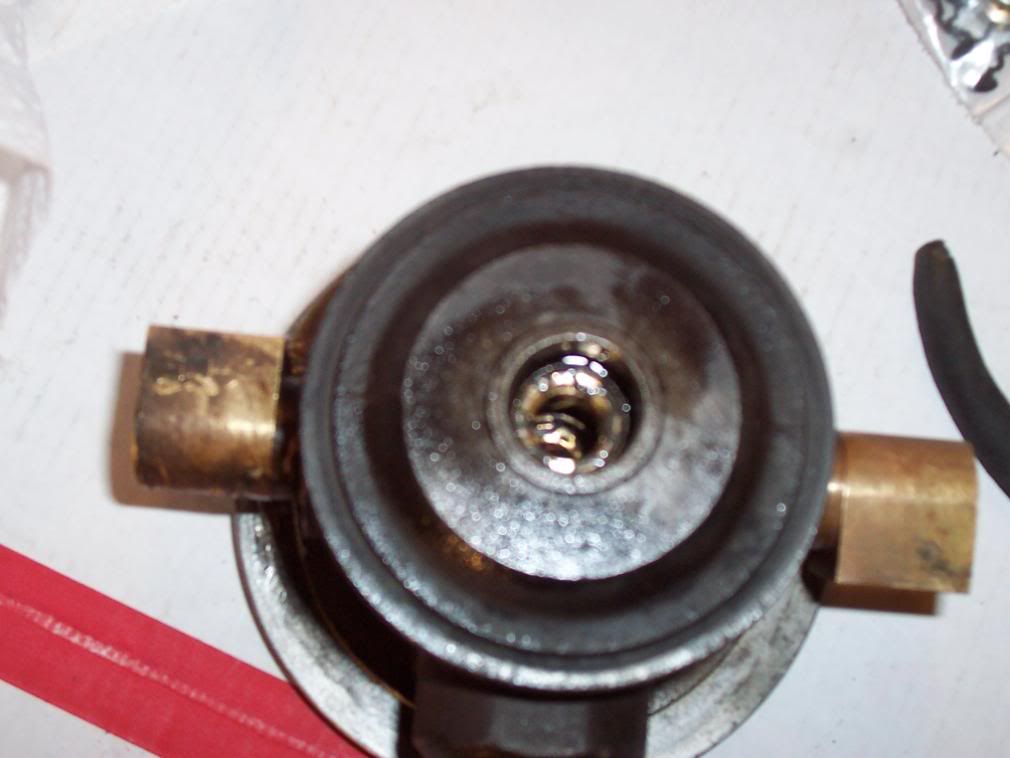
Ok take the turbine shaft and coat it 30 weight oil. Put the turbine shield back on the CBH and install the shaft into the CBH from the turbine side first. Then put the compressor vane on the front of the shaft. Install the new 12 point nut counterclockwise to tighten. Orient the vanes according to the marks, pictures or sketch you make and lock it down with the 12 mm wrench and ratchet.
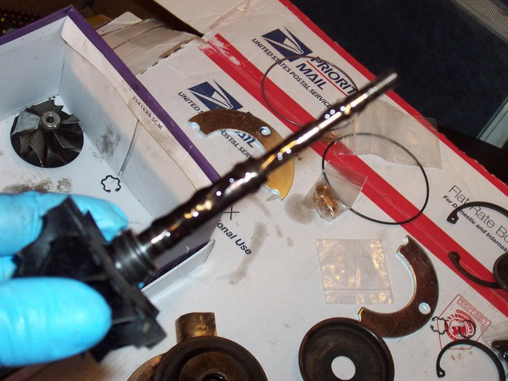
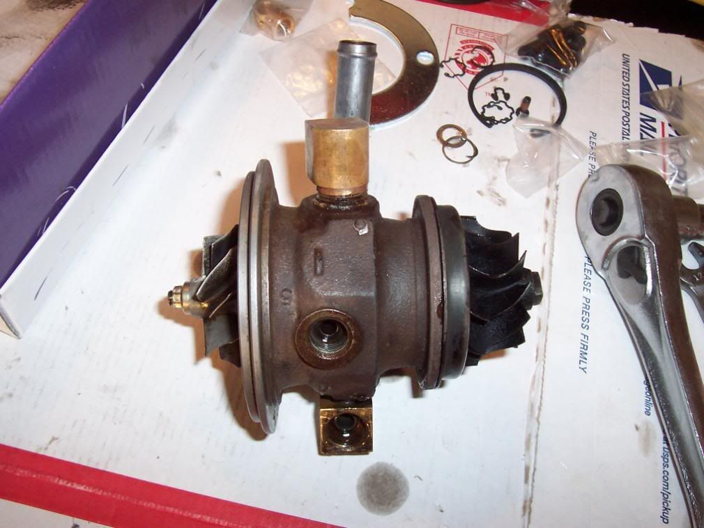
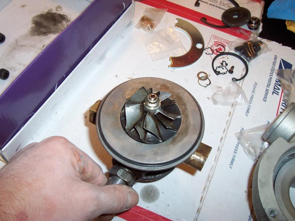
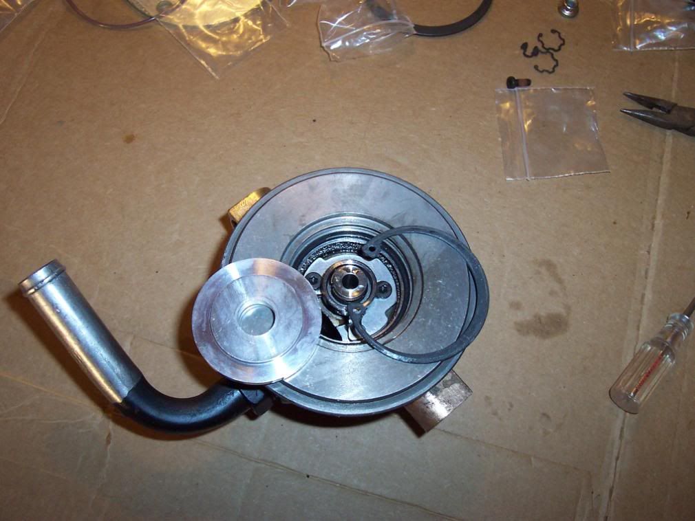
Lay a new O-Ring on the CBH compressor side like in the picture. Take the compressor housing and line up your dimple marks from before. Get that huge snap ring again and lay it on the top of the compressor housing. Install with the snap ring pliers. Make sure the tapered side is up on all these snap rings including the seal plate (should have mentioned that earlier eh?). Use a flat head screwdriver to make sure it is seated into the compressor housing groove.

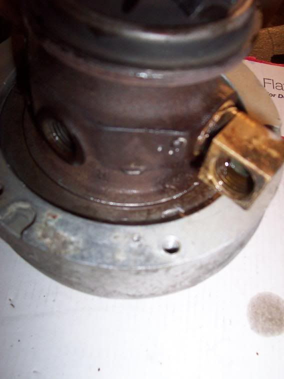
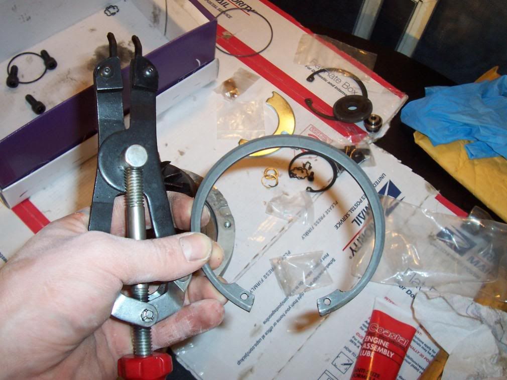
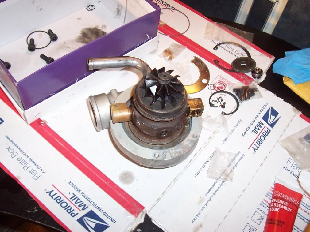
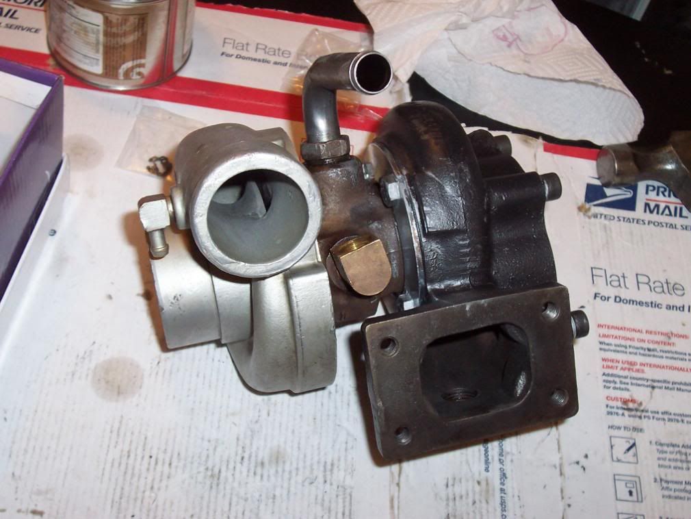
Take your turbine housing and line up it’s dimples and install the new bolts and spanner rings. Do yourself a favor and put antisieze on all the mating components including the housing where it mates to the CBH and the 13 mm bolts. This will make life a whole like simpler when you are upgrading the compressor housing and turbine to a bigger one in 6 months Wrench it all down. Grab a beer you earned it!
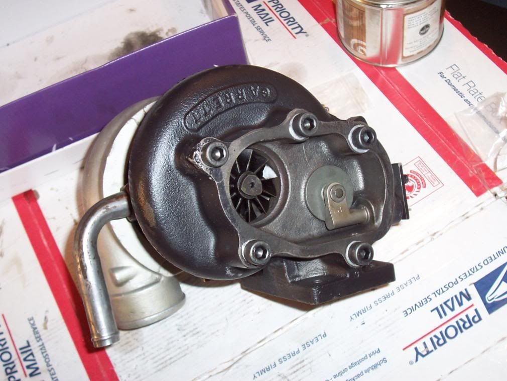
Here are some exploded diagrams of the T25 with the different seal configurations:
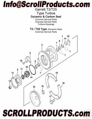
#1 Journal Bearings , 2 Sets (Narrow & Wide)
#2 Retaining Rings for Journal Bearings
#3 Retaining Ring for Oil Deflector
#4 Oil Deflector Seal/Washer
#5 Piston Ring for Turbine End
#6 Thrust Bearing
#7 Bolts for Thrust Bearing
#8 Seal Ring for Seal Plate
#9 Thrust Collar
#10 Piston Ring for Compressor End
#11 Seal Plate
#12 Retaining Ring for Seal Plate
#14 Locknut for Turbine Shaft, 0.264" (6.70mm)
#16 O-Ring for Compressor Housing
#17 Retaining Ring for Swing Valve
#18 Retaining Ring for Turbine End
#19 Bolts for Turbine End
#20 Clamps for Turbine End
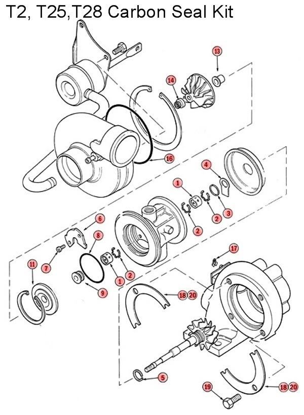
#1 Journal Bearings , 2 Sets (Narrow & Wide)
#2 Retaining Rings for Journal Bearings
#3 Retaining Ring for Oil Deflector
#4 Oil Deflector Seal/Washer
#5 Piston Ring for Turbine End
#6 Thrust Bearing
#7 Bolts for Thrust Bearing
#8 Seal Ring for Seal Plate
#9 Thrust Collar
#11 Seal Plate/Carbon Seal Assembly
#13 Thrust Spacer
#14 Locknut for Turbine Shaft, 0.264" (6.70mm)
#16 O-Ring for Compressor Housing
#17 Retaining Ring for Swing Valve
#18 Retaining Ring for Turbine End
#19 Bolts for Turbine End
#20 Clamps for Turbine End
Happy Motoring!
Ken
Lets get started:
First thing get yourself some tools and lubricants, for this project you are going to need:
-PB Blaster and lots of it
-A Clean Working Station
-1 Gallon Bucket of Chem Dip or Gunk Engine Parts Cleaner
-1 Quart of 30 weight oil
-Mini 3 Jaw Puller (I rented from Autozone see picture for p/n)
-A Large set of Internal Snap Ring Pliers (I got lucky and maintenance at work had a pair, otherwise plan on spending $120 or hunting for a pair in your local wrench heads toolbox)
-A Small set of Internal Snap Ring Pliers
-Hammer
-Various small and large flat head screwdrivers
-13 mm wrench
-12 mm wrench
-10 mm wrench
-Standard 12 point sockets and ratchet
-T15 Torx bit
-Carb Cleaner in a spray can
-1200 F ceramic spray paint
-Ebay T25 Turbo Rebuild kit (I got mine for $58 plus shipping)
-Awl or drift pin
-Paint Pen or Grease Pencil
-Wire Brush
-Paper Towels
-Time, this being my first time it took me roughly 6 hours to do this including time to let stuff soak in the chem dip
First thing, flip the turbo onto it's turbine housing and mark the relation of the turbine housing to the CBH (Center Bearing Housing). Do the same for the Compressor housing. Use the drift pin and hammer to make "dots" on each. You do not want to get this wrong when you re-assemble.
Next, soak the turbine housing (exhaust side) with PB blaster (The BEST!) around the bolts and where the metal spanner clamps are. I did this step before I actually planned on taking the turbo apart so mine was soaking for about 2 weeks, on and off as I walked by I sprayed it. If you got the time this is the safest way to make sure you don't shear any bolts in the housing.

Remove the 4 bolts and spanner clamps from the turbine housing. Your housing may or may not drop off the CBH. One my turbos did the other I had to motivate with a hammer. When you are wailing on this thing to get it out try to strike it all around not just one side otherwise it will bind up and you will get nowhere.

Being an mechanical engineer by day I have access to all kinds of goodies at work such as a particle blaster and machine shop. Thus it was no question that I took the turbine housing to work and bead blasted it as well as used a government favor to have one of the broken off studs on the downpipe flange machined out and tapped. They even gave me some nice grade 8 socket head cap screws (SHCS) for the project. You may not have access to a bead blaster or machine shop but I'm sure it would not cost all that much to have the local engine shop blast it for you or take out a bolt. Otherwise just soak it in the chem dip for a while and wire brush the housing, it's going to rust later anyways


Now put the turbo on it's compressor housing and soak the big snap ring/housing with PB Blaster. Let it soak for a while. Now prop it on it's side being EXTREMELY careful NOT to put ANY LOAD ON THE TURBINE BLADES!!!!! I cannot stress this enough you will hate yourself if you bend any of those things. Now get a big flat head and a hammer and beat the piss out of that snap ring until it moves around. I hit it on the ends trying to push them closer together. Once you get them moving a bit get the big pair of internal snap ring pliers with the correct tips and begin to compress that snap ring. When you can see the edge of it get a buddy or if you do yoga grab a medium flat head and pop the side of the snap ring out that you can get at. Don't worry about it amputating your arm as the CBH will keep it from ninja staring into the wall.


So now you got the compressor housing off, these two steps are by far the hardest and from here on in it is pretty simple and straight forward provided your guts of the turbo are good. Take the old O-Ring out of the housing. Take the compressor housing and dump it into the chem dip. Now inspect the vanes of the turbo, note any bent or worn areas. If you see anything like this I would recommend you stop and get new compressor or turbine vanes. These things are balanced much like your engine and if something is bent, worn or missing outright it will not perform properly in operation, could hit some nasty resonance during operation or hit the housing and throw chunks of metal into your engine. In any case the car will not be fast and could end up costing your a lot more money than the vanes cost so if it looks bad replace it.
I had two turbos the first one had a bent turbine vane so I opened the other turbo up and used it’s vanes and shafts.

At this point if everything looks good we are going to take the turbo apart. Before you do this make sure to mark the relation of the turbine vane to the compressor vane. This will allow you to maintain the balance of the turbo (and save you $$). After you mark it make sure to take a picture or make a sketch to make sure you put it back as close as possible. I used the tip of the compressor vane lined up to the left tip of the turbine vane. Point is find some identifying feature to line it up against, if you want you could always mark the vanes to each other and the vanes to the housing to get it dead on. I did not think of this until after I took mine apart, oh well.


Now we are ready to unbolt the shaft. Remember the nut on the compressor end is left hand threads this means it loosens by turning to the right not like all other threads on this thing. If you don’t understand what I’m saying you best not be trying to rebuild your own turbo. Take a 12 mm open end wrench and hold the turbine end and use a 12 point socket with ratchet on the compressor side. These sizes will vary, I think my compressor end was a standard socket but I forget which size. Hold the turbine end with the open end of the wrench and turn the ratchet to the right! It should crack pretty easy and you can thread the nut off.


Ok get your autozone 3 jaw puller you rented and put the jaws on the flange on the compressor end of the CBH and tighten the shaft until it pilots onto the dimple in the compressor end of the shaft. Now take a 13mm wrench or socket and turn the thread on the puller until the shaft is pressed out of the housing. BE CAFEFUL the shaft and turbine will drop out, have a towel or rags in a box for it to drop into. Again you don’t want to bend those vanes.


Don’t be a wise guy and soak them with carb cleaner to make them look pretty you will dissolve your markings. If you have to clean the vanes use a paper towel with some chem. Dip on it and carefully wipe them individually skipping the painted vanes. Take a minute and inspect the shaft for any abnormal wear on the bearing surfaces. This would include deep grooves and excessive scratches. It should be a smooth surface. Discoloration is fine as long as it is smooth. If it is really dirty like mine was take some chem dip on a paper towel and wipe down the shaft and buff it by hand with a copper wire brush to get stock on carbon off. There is a compression clip on the turbine end of the shaft, take this off with a small screwdriver and clean out the groove. Put in a new compression clip and put the shaft and vanes off to the side. Take the turbine cover plate and clean it up in the chem dip.


Now take your set of small snap ring pliers and take the snap ring off the seal plate. Using a small flat head screwdriver pry the seal plate off of the thrust bearing. The seal plate is held in with a compression clip and may take some prying around the circumference to get free. Now get a T15 torxs bit and remove the two bolts holding the thrust bearing plate in. Remove the thrust bearing. Check the thrust bearing for excessive thrust clearance and check the surfaces for excessive wear. You may be able to reuse this at a late date if it is not worn out so save it.


Remove the compressor radial bearing by using a small flat head screwdriver to pop it out by pulling it up on the inner diameter

Use a small flat head screwdriver to pry out the snap ring holding in the radial bearing on the turbine side. Remove the radial bearing. Inspect all bearings for abnormal wear on the ID (inner diameter) and OD (outer diameter). Normal wear would be for a polished silver surface on the ID. Abnormal could be a silver surface on only one side, this is called taper and could mean there is a problem with the CBH. Make sure the OD is not worn down too much such as the surface is silver instead of gold. This means the bearing was spinning in the housing instead of the shaft spinning inside of it’s ID. If the OD is all silver like the ID, then you should take your CBH to get measured to make sure the radial clearance is right when you put in the new bearings. Per flybynite: 003-.0035 of an inch clearance on the o.d. and .0012-.0016 of an inch on the i.d. it the proper clearance.


At this time take out the compressor housing from the chem dip and clean it off with some paper towels.

Ok now dump the entire CBH into the chem dip. Let it soak for at least 1 hour and wire brush it and soak it again for 20 minutes min. Take it out and flush it with carb cleaner inside and out to get all the chem dip out and carbon debris. Make sure the bearing surfaces are especially clean and dry. Make sure the oiling holes are cleaned out and not all clogged up with carbon. Now that everything is clean take one of radial bearings and dip it in the 30 weight oil. Drop it into the compressor side of the housing. Now take your new thrust bearing and install the new compression ring supplied. Take the thrust bearing assembly and plate and coat the thrust bearing surfaces with 30 weight oil. Assemble the two. Now take the new seal plate and pop it onto the OD of the thrust bearing where the compression clip is. Make sure the thrust bearing rotates freely in the seal plate. If it does not remove it and reuse your old seal plate. I found my new seal plate did not line up right and had to reuse the old one. Now disassemble the seal plate from the thrust bearing, that was just practice because if it does not line up right after you have the thrust bearing torqued it…you will have to drill out the seal plate if it binds up (speaking 1st hand on this one) and redo all the cleaning and assembly again. Line up the thrust bearing assembly and screw them down. Make sure they are tight. Next take a new O-ring and lay it into the groove in the CBH. Take the new seal plate and pop it into the thrust bearing OD like before. Again make sure the seal plate and thrust bearing can rotate with respect to one another. Secure the seal plate with the snap ring.


Flip the CBH over and install the new turbine radial bearing. I also forgot to mention if you like you can replace the inner snap rings in the CBH with new one supplied in the kit. Mine were seated nice and showed no wear so I left them in there to make life simple. Secure the turbine radial bearing with a new snap ring. Make sure it is seated in the groove properly by pushing on it with a flat head to see if it pops out and shoots across the room. You don’t want your radial bearing to walk around in that housing.

Ok take the turbine shaft and coat it 30 weight oil. Put the turbine shield back on the CBH and install the shaft into the CBH from the turbine side first. Then put the compressor vane on the front of the shaft. Install the new 12 point nut counterclockwise to tighten. Orient the vanes according to the marks, pictures or sketch you make and lock it down with the 12 mm wrench and ratchet.


Lay a new O-Ring on the CBH compressor side like in the picture. Take the compressor housing and line up your dimple marks from before. Get that huge snap ring again and lay it on the top of the compressor housing. Install with the snap ring pliers. Make sure the tapered side is up on all these snap rings including the seal plate (should have mentioned that earlier eh?). Use a flat head screwdriver to make sure it is seated into the compressor housing groove.


Take your turbine housing and line up it’s dimples and install the new bolts and spanner rings. Do yourself a favor and put antisieze on all the mating components including the housing where it mates to the CBH and the 13 mm bolts. This will make life a whole like simpler when you are upgrading the compressor housing and turbine to a bigger one in 6 months Wrench it all down. Grab a beer you earned it!


Here are some exploded diagrams of the T25 with the different seal configurations:

#1 Journal Bearings , 2 Sets (Narrow & Wide)
#2 Retaining Rings for Journal Bearings
#3 Retaining Ring for Oil Deflector
#4 Oil Deflector Seal/Washer
#5 Piston Ring for Turbine End
#6 Thrust Bearing
#7 Bolts for Thrust Bearing
#8 Seal Ring for Seal Plate
#9 Thrust Collar
#10 Piston Ring for Compressor End
#11 Seal Plate
#12 Retaining Ring for Seal Plate
#14 Locknut for Turbine Shaft, 0.264" (6.70mm)
#16 O-Ring for Compressor Housing
#17 Retaining Ring for Swing Valve
#18 Retaining Ring for Turbine End
#19 Bolts for Turbine End
#20 Clamps for Turbine End

#1 Journal Bearings , 2 Sets (Narrow & Wide)
#2 Retaining Rings for Journal Bearings
#3 Retaining Ring for Oil Deflector
#4 Oil Deflector Seal/Washer
#5 Piston Ring for Turbine End
#6 Thrust Bearing
#7 Bolts for Thrust Bearing
#8 Seal Ring for Seal Plate
#9 Thrust Collar
#11 Seal Plate/Carbon Seal Assembly
#13 Thrust Spacer
#14 Locknut for Turbine Shaft, 0.264" (6.70mm)
#16 O-Ring for Compressor Housing
#17 Retaining Ring for Swing Valve
#18 Retaining Ring for Turbine End
#19 Bolts for Turbine End
#20 Clamps for Turbine End
Happy Motoring!
Ken




Comment