Announcement

Collapse
No announcement yet.

Manifold Volume for a L82 3100???

Collapse
This topic is closed.
X
X
 
  • Filter
  • Time
  • Show
Clear All
new posts

  • Manifold Volume for a L82 3100???

    Working on a Physics formula involving heat transfer through iron and aluminum from coolant to intake air charge.

    I am building the formula to get a very precise charting of temperature differences from the IAT Sensor versus the Intake Valve.

    I will share my results when finished, including some really neat spark maps resulting from such formulas as well.

    Sooo, any know the volume of the Plenum, Lower Intake Manifold and the intake bowl in the heads? Please help, I am desperate and I REALLY don't want to take my engine apart to get these figures!!!

  • #2
    I think I figured it out once... I'd have to dig through a bunch to find it....
    -Brad-
    89 Mustang : Future 60V6 Power
    sigpic
    Follow the build -> http://www.3x00swap.com/index.php?page=mustang-blog

    Comment


    • #3
      Originally posted by bszopi View Post
      I think I figured it out once... I'd have to dig through a bunch to find it....
      Cool, in return I share the results if your interested. Doing the real deal physics. Thermal Conductivity (J/s*m*C)

      Q=kA ∆t ((T2-T1)/L
      k=Constant Thermal Conductivity of Aluminum = (J/s*m*C) = 238
      A= Surface Area of Heat Transferred (area of intake system)
      ∆t=Time in seconds
      T2=ECT in C
      T1=IAT Temp in C
      L=Depth of Aluminum/Iron (thickness)
      Q= Joules of energy transfered

      Taking Q we can then get how much temp the air absorbed per second....
      Q=mc∆T
      Q = Joules
      m = AirMass in kilograms
      c = specific heats of the substance (air) in (J/kg*Cdeg) = 1.009
      ∆T = Temp in C

      or Q/(mc)=∆T This will give the final intake air temp as it enters the valve pocket. From there I may attempt further with valve temps and the effects of fuel vaporizing.

      I hope you find it, thanks!

      Comment


      • #4
        I never measured a small port 3100. Maybe an intake port on a head, but I don't recall. Would be with the flowsheets on the site. How are you going to account for the combustion temperature vs load, and the quality of contact between the seat and valves. You would need to know the width of the seat and the cam specs. I can't imagine computing all of that to find an intake valve temperature. Have you checked how the newer OEM computers calc for fuel based on temp for the film on the intake port walls? Simply amazing stuff to have to consider for the emissions and efficiency.
        Ben
        60DegreeV6.com
        WOT-Tech.com

        Comment


        • #5
          Originally posted by SappySE107 View Post
          I never measured a small port 3100. Maybe an intake port on a head, but I don't recall. Would be with the flowsheets on the site. How are you going to account for the combustion temperature vs load, and the quality of contact between the seat and valves. You would need to know the width of the seat and the cam specs. I can't imagine computing all of that to find an intake valve temperature. Have you checked how the newer OEM computers calc for fuel based on temp for the film on the intake port walls? Simply amazing stuff to have to consider for the emissions and efficiency.
          When there is will there is a way. This particular pursuit has more to do with a special spark mapping system and I need a rough but general idea how ECT effects the intake charge. It won't be too hard to calculate how much thermal energy is conducted through the block then the LIM. At some point I will attempt to also include ambient temps as well outside the LIM.

          The spark mapping is quite a unique idea. AND I was able to get my idle to vary ONLY +/- 12 RPM!!! Very smooth.

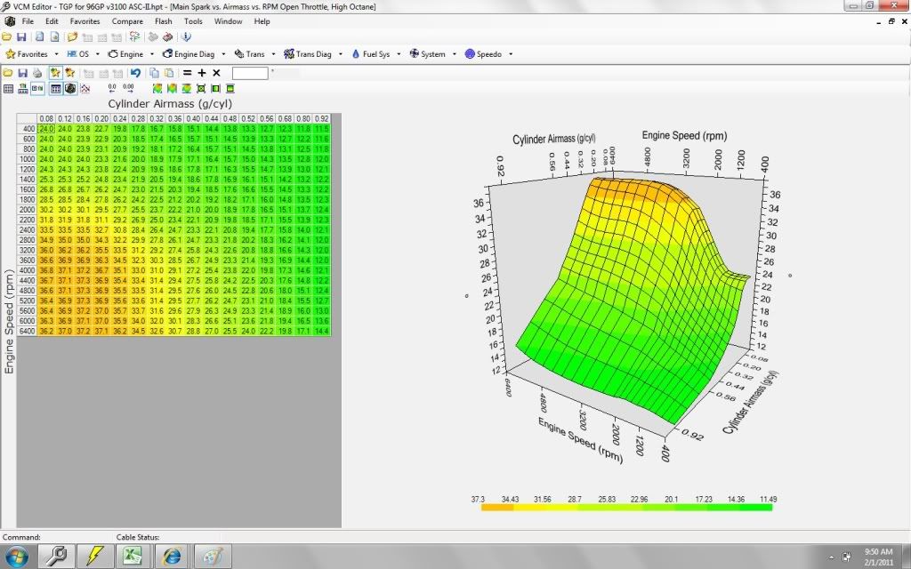
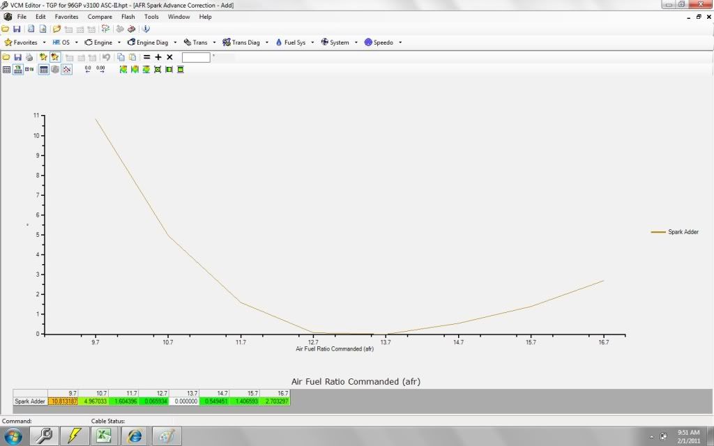
          I utilized the AFR vs Spark Adder table and adjusted the spark degree to reflect the change in flame front at various AFR's. I found 2 studies regarding that exact subject and interpolated their data and calibrated the curve from the base reference point of 800 RPM at 13.5 AFR with 18 Degrees Spark Idle. As the AFR get richer or leaner from 13.5 (the fastest burning AFR) the Degree is skewed to match the extra delay.


          Because of the new offsets in a table that was once blank stock I had to adjust the Main Spark Maps according to average AFR per cell. I found this newer table appeared to be as simple as two curves, one horizontal the other vertical (RPM vs Airmass). This map also appeared a lot like the theoretical torque spark map foound in later PCM's. So I created the High Octane table by averaging together the two curves and based out the idle cells.


          The IAT Spark adder table was easy. It was a simple ratio of density which was extrapolated from one of the spark curves I had earlier for the High octane map. I kept the high temp cells as spark retard to prevent detonation, ect.

          Now I need to tune in the ECT Spark Adder table.

          Hopefully I can create a curve template for all spark tables and then adjust each table slightly to find the right intensity. If all goes well the peak pressures should all fall closer to the target 12*ATDC since Flame Front Speeds are now being compensated for to retain the same time on target concept. So adjusting the maps up/down will adjust the Peak Pressure point ATDC equally across all RPM/Airmass.

          Phew, thats a lot to type. Hard to explain entirely.

          Comment


          • #6
            Question... How is this done? Would you measure the volume of the IMs by taping or sealing off each opening with say, thin plastic plates held by some silicone sealer and after standing them on end, fill them completely with water? After that, couldn't you pour the results into a container and make it easier to calculate known weight and volume?
            Last edited by 60dgrzbelow0; 02-03-2011, 11:43 PM.

            Comment


            • #7
              Basically, yes.

              Droid via Tapatalk
              -Brad-
              89 Mustang : Future 60V6 Power
              sigpic
              Follow the build -> http://www.3x00swap.com/index.php?page=mustang-blog

              Comment


              • #8
                Originally posted by 60dgrzbelow0 View Post
                Question... How is this done? Would you measure the volume of the IMs by taping or sealing off each opening with say, thin plastic plates held by some silicone sealer and after standing them on end, fill them completely with water? After that, couldn't you pour the results into a container and make it easier to calculate known weight and volume?
                Originally posted by bszopi View Post
                Basically, yes.

                Droid via Tapatalk
                Well, I wouldn't measure how much water pours out of the manifold, thats messy. Rather, keep track of how much is being poured in.

                If I were to do it....I would get a pair of good heads (or the actual heads are even better for accuracy) and assemble the intake system off the engine. Basically bolting the LIM to the Heads and the Plenum to the LIM. Seal off the vacuum line ports and use a rubber grommet like plug soaked in oil for the Fuel Injector ports.

                Pour the fluid (water or oil) into the setup measuring the amount put in. Once the runners are full, tilt sideways while filling up to the brink of the Throttle opening to avoid air pockets in the runners.

                That is the best accuracy I would imagine for a DIY at home job. If each piece is done seperately, we must add the volume of the gaskets.

                The only thing left would be the volume from the TB just behind the Throttle Plate.

                Looks like I will have to wait to do this when I replace a head gasket or do some work on the Heads/Pistons.
                Last edited by Schmieder; 02-05-2011, 02:07 PM.

                Comment


                • #9
                  Quite an Interesting problem. If it would not shake your test IM where it is bench mounted too much, you could clear any trace air trapped inside by lightly applying external vibration (vibrating sander over a piece of a rubber bicycle tire for example) for just a moment or two ...before your fluid level gets too far filled up and winds up vibrating the liquid out of the edge of the throttle body manifold. If done incrementally ...no air would remain inside..

                  On a tangential line ...these two articles 'resonate to some degree' with what you are working on...


                  Last edited by 60dgrzbelow0; 02-06-2011, 12:34 AM.

                  Comment


                  • #10
                    I will be tearing into my engine once more during my Getrag 282 swap. I want a better then OEM cam grind for the turbo and I'm going to try installing 1.65:1 Harland Sharp Roller Rockers. If I have to grind the LIM and/or the rocker side profiles to fit, I will. If I get them to fit and work properly I'm sure I could quickly fit 1 more set if anyone is interested. This will happen in a few weeks time.

                    During that time I will get the manifold volume for both the L82 (small port 3100) and the 3400 since I am also dropping in the wide runner 3400 LIM/Plenum.

                    Comment


                    • #11
                      you know, even in the $A1 mask, the ECM takes coolant temp, airflow, air temp, engine runtime and a few other variables to create an estimated "manifold runner temp" value, which is used in the speed-density equation IIRC. otherwise, it may just be used for AE/DE purposes.

                      i'd be very surprised if the OBD2 PCMs don't do the same, if not more already.
                      1995 Monte Carlo LS 3100, 4T60E...for now, future plans include driving it until the wheels fall off!
                      Latest nAst1 files here!
                      Need a wiring diagram for any GM car or truck from 82-06(and 07-08 cars)? PM me!

                      Comment


                      • #12
                        Originally posted by robertisaar View Post
                        you know, even in the $A1 mask, the ECM takes coolant temp, airflow, air temp, engine runtime and a few other variables to create an estimated "manifold runner temp" value, which is used in the speed-density equation IIRC. otherwise, it may just be used for AE/DE purposes.

                        i'd be very surprised if the OBD2 PCMs don't do the same, if not more already.
                        Hmm, I should look into that. Understanding thier formula could bring some insight into my madness, hehe.

                        Comment


                        • #13
                          i have the code for it, possibly summarize it, might help.
                          1995 Monte Carlo LS 3100, 4T60E...for now, future plans include driving it until the wheels fall off!
                          Latest nAst1 files here!
                          Need a wiring diagram for any GM car or truck from 82-06(and 07-08 cars)? PM me!

                          Comment


                          • #14
                            Originally posted by robertisaar View Post
                            i have the code for it, possibly summarize it, might help.
                            Yeah, anything which can dissolve some mystery behind the PCM's calculations. Do you have any information on how the AE is calculated by specifics of each table? I tried to find any correlations in excel from tons of logs, didn't find any. But I did manage to get the AE and DE to have almost no dips or spikes at all practical ECT's. But that took sooooo much time.

                            Comment


                            • #15
                              AE is going to be quite different, i can say that much.

                              comparing MAF with MAP, assuming the OBD2 PCMs use the MAF for AE/DE calcs.
                              1995 Monte Carlo LS 3100, 4T60E...for now, future plans include driving it until the wheels fall off!
                              Latest nAst1 files here!
                              Need a wiring diagram for any GM car or truck from 82-06(and 07-08 cars)? PM me!

                              Comment

                              Working...
                              X