Announcement

Collapse
No announcement yet.

TDCTT build.......MegaII

Collapse
X
 
  • Filter
  • Time
  • Show
Clear All
new posts

  • TDCTT build.......MegaII

    Small update.. Started working on my stand alone the other day. Had redo the factory work, (did'nt like the workmanship) and lengthen the overall harness. I'd picked up the properly labeled wires a while back. The wires have label of where they go written into their coatings. Makes life a little easier for the installer (me).

    This is the original set up. There was nothing to support the wires where they entered the ECM plug. Looked like a weak spot to me.


    This is after I removed the factory crap covering.


    I desided to wheather proof the 2 areas @ the factory crimpings for added strength and protection with heat shrink tubbing.


    Now a bundling layer @ the base of the plug and running down about 8 or so inches.


    Next I soldiered the wire ends to their corresponding wires..


    Heat shrinking each of them aswell.


    Then using a long length of heat shrink tubbing, I covered the harness to about 2/3 the total length. As you can see I also fused the cable to the plug for added harness durability @ the plug end.

  • #2
    Also ordered, boost controller, plug and play pig tail connecter, extra 23" length labeled wires for megaII, Performance fuel pressure reg, and USB adapter wire for touch screen to ECM connection, and boost mod kit..


    Comment


    • #3
      Update:

      Spent some of Fri, Sat, and Sunday, Building my stand alone engine managment system kit.

      Just had to put the contents of these "couple" lol, bags on the blank board.


      An idea of the size of components I'm working with..


      Starting @ the top of the bare board. (FET) placement etc. And temporarly tape them in place.


      This is the tip on the soldering iron I used. It's plated so not to let solder stick to it.

      Soldered then afterwards clip the ends off with mini end cutters.


      Each small bag denotes it's contents and Alpha Numeric placement and pole direction (if nessasary).

      For example: These are diodes that only let current flow in one dirrection.


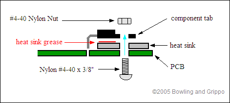
      After the first few pieces are in place I removed the tape and used 4 Nylon bolts and nuts. This is temporarily to hold the board up for further piece placement.


      Then repeat and continue with each tiny circuit.


      Them bolted on the end panels.


      Then installing a 40 pin riser bridge, for the Daughter board which just presses in place.


      Daughter board: (factory assembled).


      Daughter board installed, and heat transfer paste (white) on the backs of the (FETS) and transitors.

      The small hole is for a vacuum line for the "on board" MAP.

      Then on to the grounded heat sink. It's the long plate across the (FET's).

      After all checks are made and everything is inspected or gone over to be sure it works I place the lid on the unit.


      The finished unit and harness connected:

      Comment


      • #4
        Just thought I'd add.

        Here's the Touch Screen LCD connected to the ECM. It's the largest LCD they carry for the module.

        Comment


        • #5
          Looks nice. That reminds me I need to pick up some more heat shrink for when I make my OBD1.5 to OBDI harness. I can't wait to see what my car does tuned.

          Touch screen??? wow got a link to a build thread?

          Is your 3.4 turbo'ed already? Is it going to be Twin Turbo? Going to be tight fitting!


          EDIT: Those components aren't bad. Those are standard size. You should try soldering with that size tip some SMD grain of sand stuff! LOL I had to once by not by choice hahah. I've found tips that solder doesn't stick to to be a PITA. I can't solder with something that doesn't flow and tin easily.
          Last edited by IsaacHayes; 09-21-2009, 08:21 PM.
          sigpic New 2010 project (click image)
          1994 3100 BERETTA. 200,000+ miles
          16.0 1/4 mile when stock. Now ???
          Original L82 Longblock
          with LA1, LX9, LX5 parts
          Manifold-back 2.5" SS Mandrel Exhaust. Hardware is SS too.

          Comment


          • #6
            Here ya go..

            Comment


            • #7
              Originally posted by IsaacHayes View Post
              Looks nice. That reminds me I need to pick up some more heat shrink for when I make my OBD1.5 to OBDI harness. I can't wait to see what my car does tuned.

              Touch screen??? wow got a link to a build thread?

              Is your 3.4 turbo'ed already? Is it going to be Twin Turbo? Going to be tight fitting!


              EDIT: Those components aren't bad. Those are standard size. You should try soldering with that size tip some SMD grain of sand stuff! LOL I had to once by not by choice hahah. I've found tips that solder doesn't stick to to be a PITA. I can't solder with something that doesn't flow and tin easily.
              Not yet, but getting there have a bunch of fab work yet. I'm relocating the batt, windsheild rez, coolant rez, removing AC, smaller master cycl and booster, and on and on lol..

              I have fat fingers lol, hard to hold stuff too much smaller haha..

              Comment


              • #8

                The heat sink bar is supposed to be bolted to the board, along with all your FET's.


                I almost made the same mistake and came dangerously close to cutting the leads too short to correct it. The "fuses" (the OHMITE components you have laying down) are also supposed to be heat sinked. The case is designed to engage that heat sink bar for thermal transfer.
                '97 Chevy Lumina, '99 LA1, ported heads, manifolds, 2 1/2" exhaust, k&n filter, 180* stat, A/C delete, Ram air, 3600 FAFB converter, 4T60E shift kit, DHP Power Tuner, AEM UEGO, MegaSquirt II/Extra

                1/8 mile 9.72@75 mph, 2.0 60 foot


                Comment


                • #9
                  Originally posted by Monzsta View Post

                  The heat sink bar is supposed to be bolted to the board, along with all your FET's. I almost made the same mistake and came dangerously close to cutting the leads too short to correct it. The "fuses" (the OHMITE components you have laying down) are also supposed to be heat sinked. The case is designed to engage that heat sink bar for thermal transfer.
                  Yeah I realized this myself later and corrected it. The lid would'nt fit on it. Thanx for the input though..

                  Comment


                  • #10
                    Cool beans... I'm about to throw mine on as a piggyback for a leaner cruise ratio. (16.5:1). I've been reading too many hypermileing boards...
                    '97 Chevy Lumina, '99 LA1, ported heads, manifolds, 2 1/2" exhaust, k&n filter, 180* stat, A/C delete, Ram air, 3600 FAFB converter, 4T60E shift kit, DHP Power Tuner, AEM UEGO, MegaSquirt II/Extra

                    1/8 mile 9.72@75 mph, 2.0 60 foot


                    Comment


                    • #11
                      Originally posted by Monzsta View Post
                      Cool beans... I'm about to throw mine on as a piggyback for a leaner cruise ratio. (16.5:1). I've been reading too many hypermileing boards...
                      Yeah it came as one of those "OH F^*K" moments. Big duh on my part lol..

                      Comment

                      Working...
                      X