This write up is for creating Custom Ignition Wires for the 96-97 3.4 DOHC Engine.
I used the MSD parts to create these items.
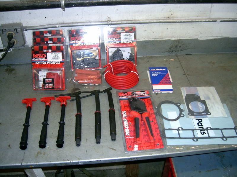
Here is the list of parts you will need.
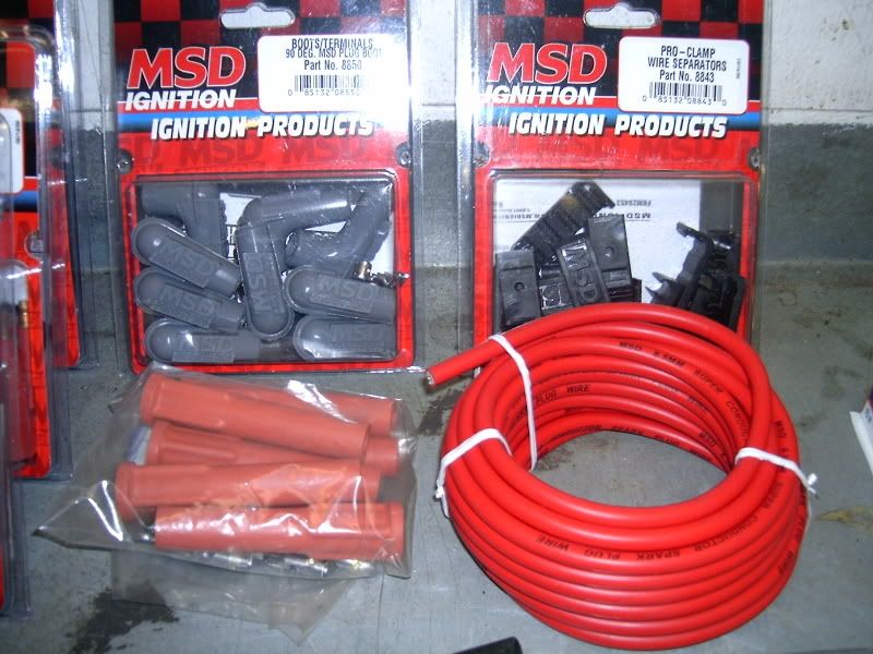
MSD 25' 8.5mm Ignition Wire #35019 x1
MSD Ignition Coil #8224 x3
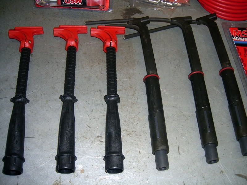
MSD 90Deg Boots/Terminals #8850 x1pkg
MSD High Heat Straight Boots #8854 x1pkg of 8
MSD Hemi-Tubes #3475 x3
MSD Wire Separators #8843 x1pkg
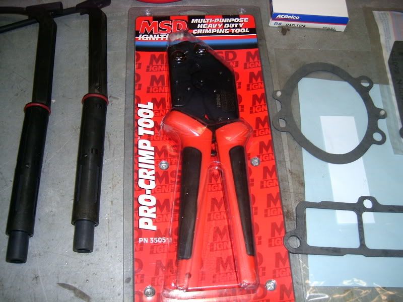
MSD Pro-Crimp Tool #3505
AC Delco Plugs #R42LTSM
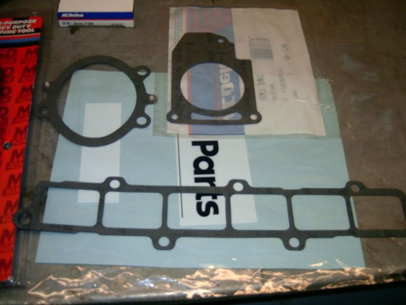
GM Gaskets: Throttle Body Gasket, UIM Gasket, Intermediate Intake Tube Gasket
1991-1995 3.4 DOHC Rear Plug Boots or add x3 Hemi Tube Boots for alternate design.
Dielectric Greese

PRE-STEP
Familiarize yourself with how to install a connector onto a piece of wire. Try this several times until you feel confident with how to do this proceedure as it will make a difference with your wires working or not. Use an old wire for reference or talk to someone that knows how and is willing to show you.
STEP 1
Removal of the Upper Intake Manifold(UIM)
The bolts should all be 10mm.
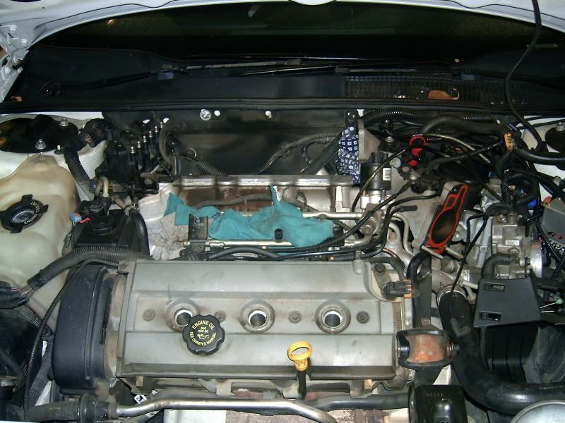
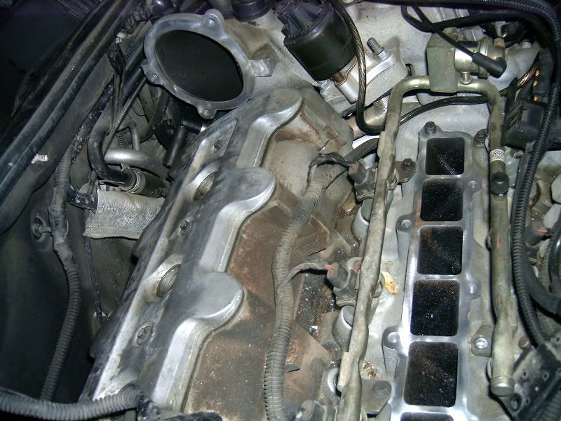
First step is to remove the UIM cause the rear plugs on the 96-97 DOHC are fully covered by the UIM.
There are three bolts on the Intermediate intake pipe to the UIM.
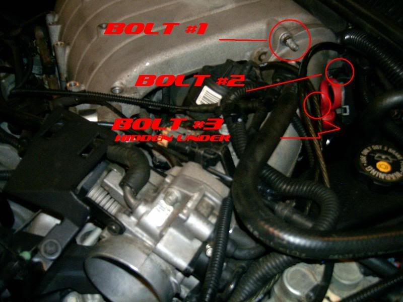
While you are in that area remove the PCV Tube from the UIM. YOu will find it right there by the bolt closest to the firewall.
Now there are (7)Bolts holding down the UIM
There are (2)Bolts holding the Coils to the UIM and
YOu have to remove the EGR bracket held on with (2) Nuts on top of the bolts then you remove #9 Bolt holding down the UIM
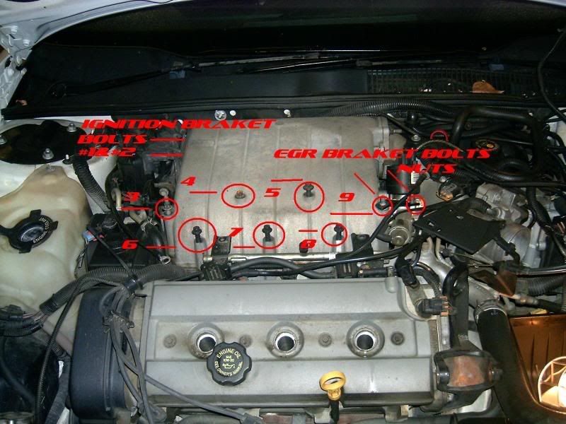
Now the UIM will come off, with a little tap with a soft malet and a wiggle it will come off.
I now removed the Ignition Wires once the UIM was off.
STEP 2
TB Gasket Replacement.
IF you are going to be replacing the UIM and Intermediate Gaskets you may as well replace the TB Gasket.
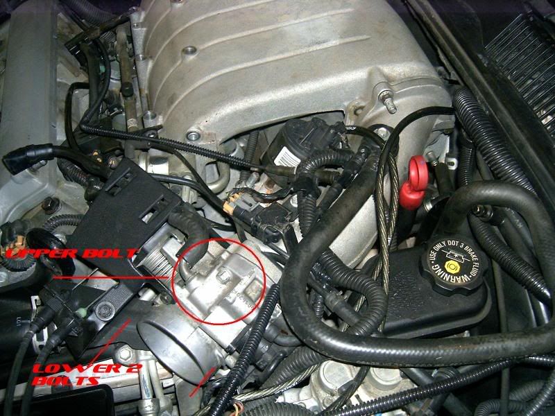
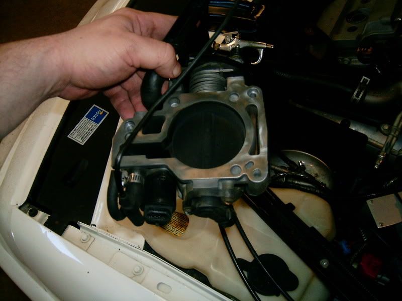
The TB is held on with only Three (3) Bolts. One is on the top of the TB and the other two hold the bracket to the TB going into the intermedate tube. I removed the TB, and cleaned up the mating surface, then reinstalled a NEW gasket (GM) and re-installed the TB. For mating surface cleaning see STEP 4.
STEP 3
Lubricating the Spark Plugs
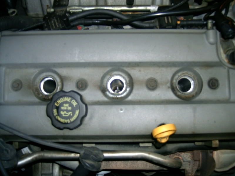
Since I have no idea when the plugs were last changed I sprayed the plugs down liberally with some liquid wrench and let them sit over night.
STEP 4
Cleaning up Mating Surfaces
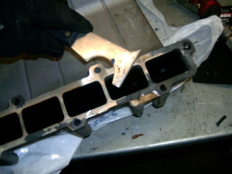
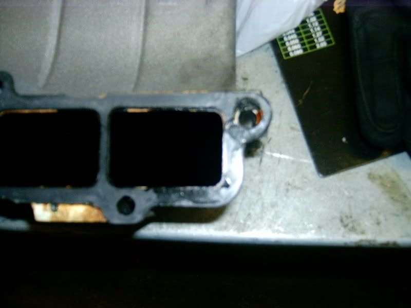
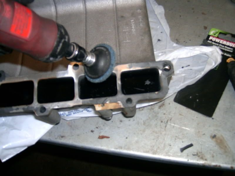
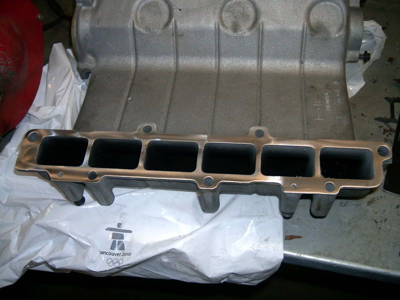
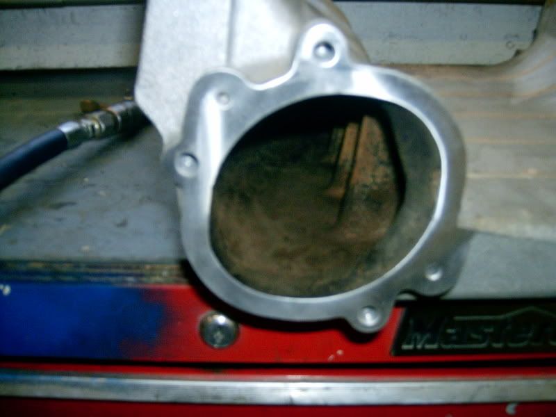
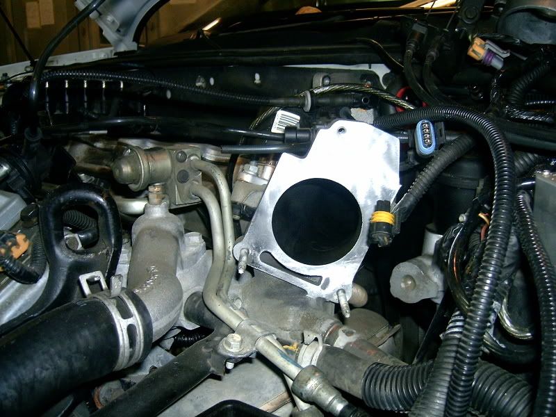
Remove all gaskets and clean up the mating surfaces to make sure that there will be no vacume leaks. This is done to the UIM, Intermediate Tube and TB. Where ever there was a gasket going it was cleaned up.
First I used a 2" metal scraper being careful not to gouge the aluminum, then I moved to a air powered grinder with a nylon disk. THe disk is just course enough to remove the old gasket materal and polish the metal but not scrap it.
STEP 5
Spark Plug Cleaning and Gapping
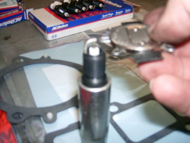
When installing new spark plugs you must always check the gap and give them a little cleaning.
I first started with the cleaning and then gapped the plugs.
I cleaned off both ends with a wire wheel attached to a bench grinder. I then used 100grit sand paper to square off the ends of the electrode and ground for a sharp spark contact.
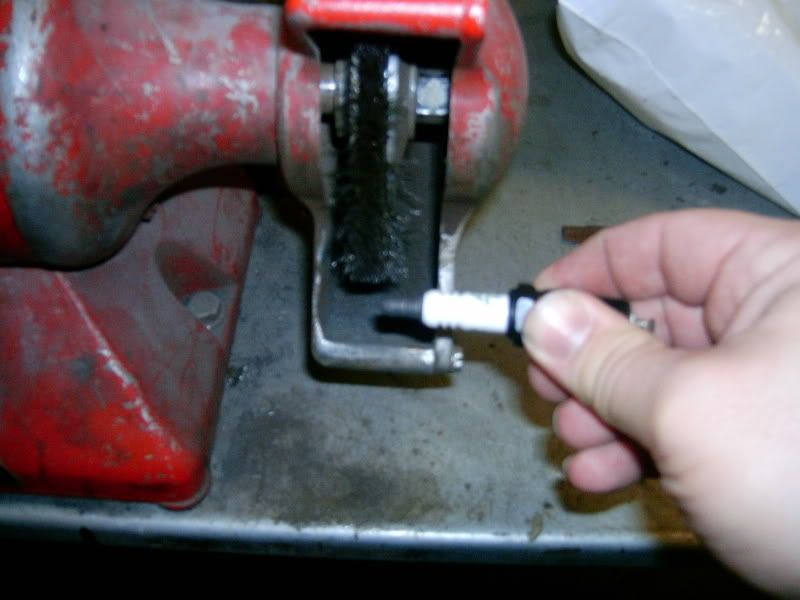
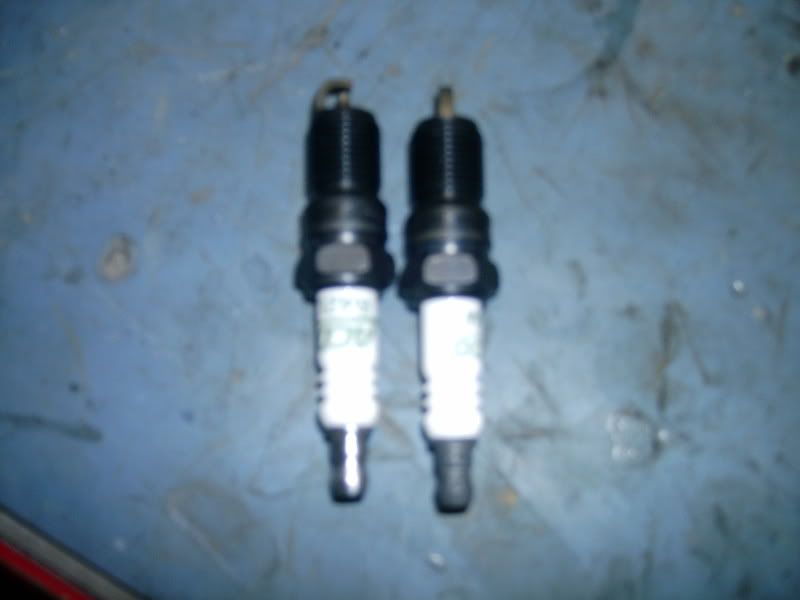
CLEANED
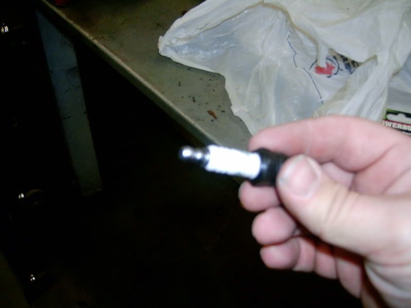
COMPAIRED
Now gap the plugs.
STEP 6
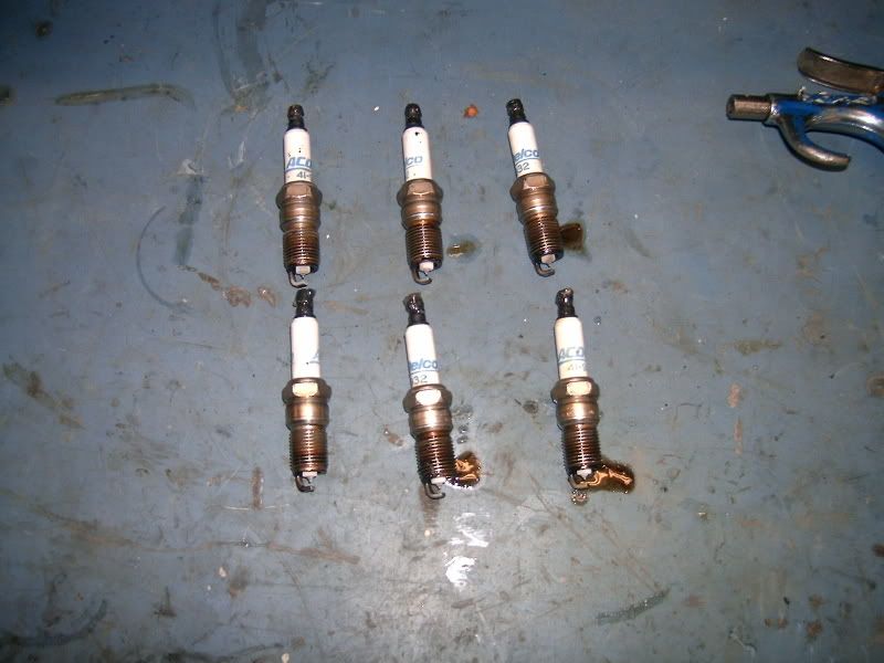
Spark Plug Removal
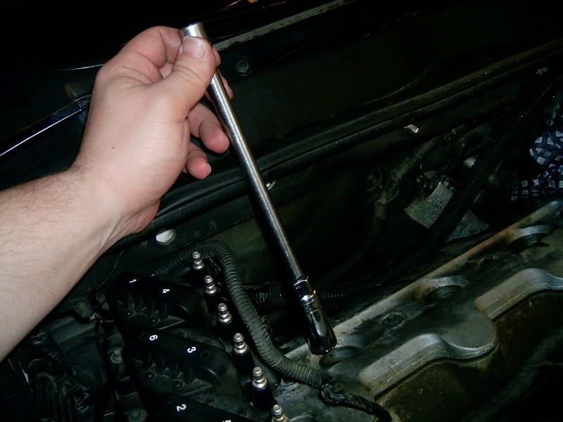
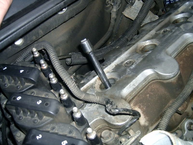
To remove the plugs I first tested to see what extensions I would need to get down the long tube. I then very carefully loosened the plugs. Taking note when laying them down to inspect them for any erreularities.
STEP 7
Spark Plug Replacement
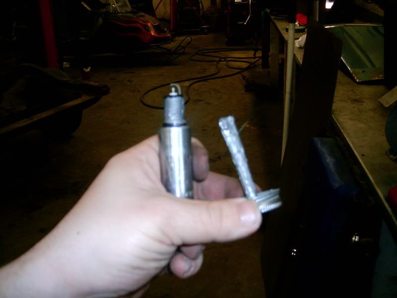
Now with the old plugs out, it is time to install the new plugs.
I used anti-seize compound on the threads to help with removal at a later time if need be.
I also recheck the gap just before installation.
STEP 8
Coil Replacement
This step is only for those that are replacing the Coils as well. If you are not replacing the coils please skip this step.
The Ignition COntrol Modual has (3) plugs connected. Remove these.
The coil/ICM is held on with three 8mm bolts to a braket. Remove these bolts so that you can work on the coil/modual on a bench.
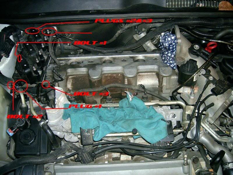
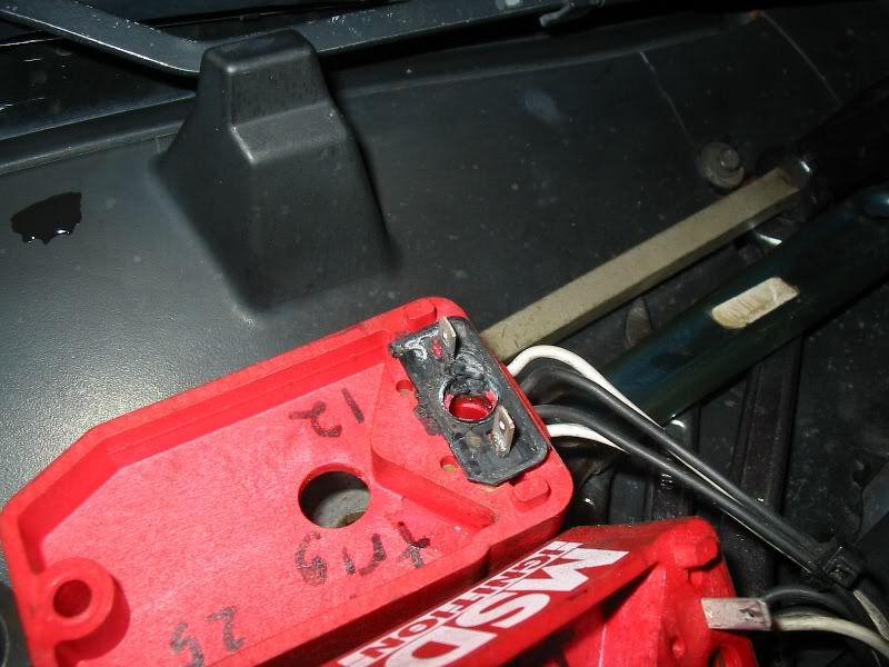
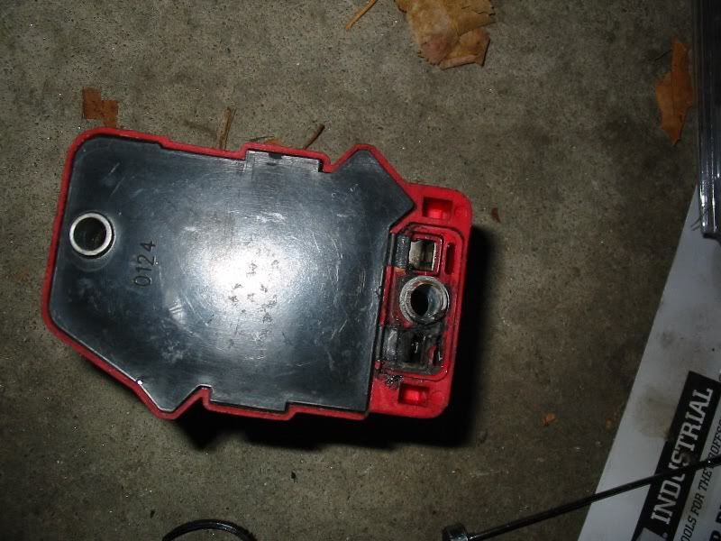
Now with the Coil/ICM on the bench we can remove the coils.
The coils are held on with 5.5mm bolts. x2 5.5mm bolts for each coil.
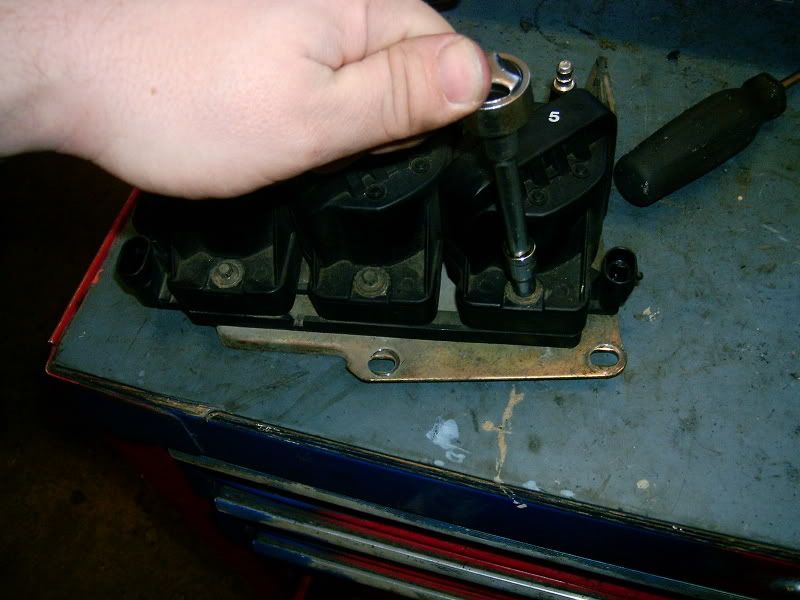
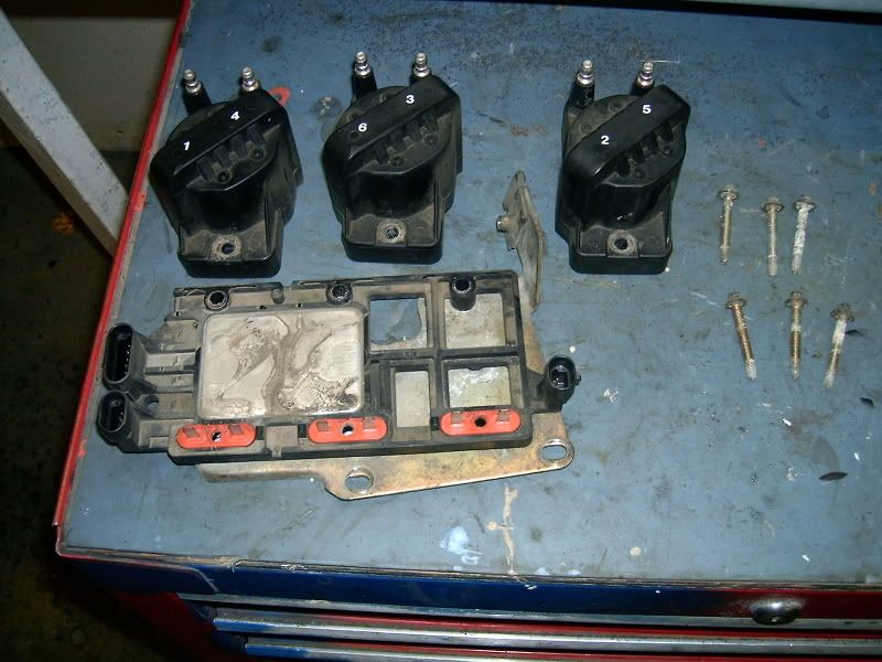
Now the NEW coils can be installed.
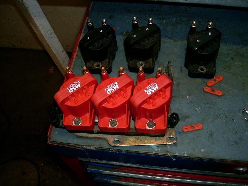
Re-install the Coil/ICM first bolting back in place then replacing he plugs.
----------------------------------------------------------------------------------------------------------------------
Now we are into building the Spark Plug Wires.
STEP 9
Rear Head Plug Building
Using the 91-95 3.4 DOHC rear boots we will build the rear plug wires.
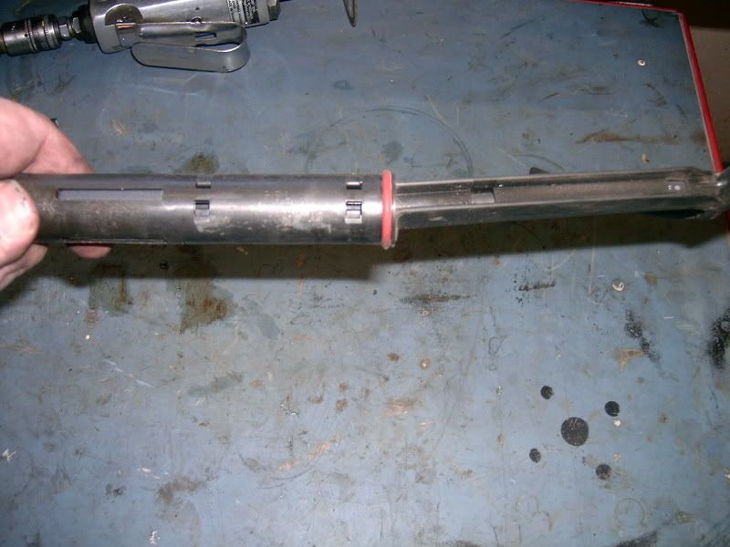
These factory boots/tubes separate. There are 4 tabs. Using a pair of needle nose pliers. Once we separate the parts the factory rubber boots can be removed.
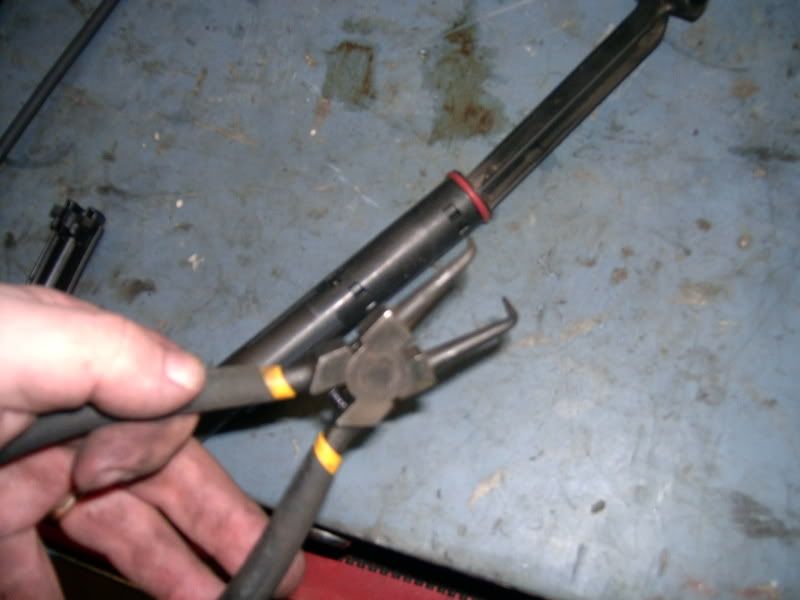
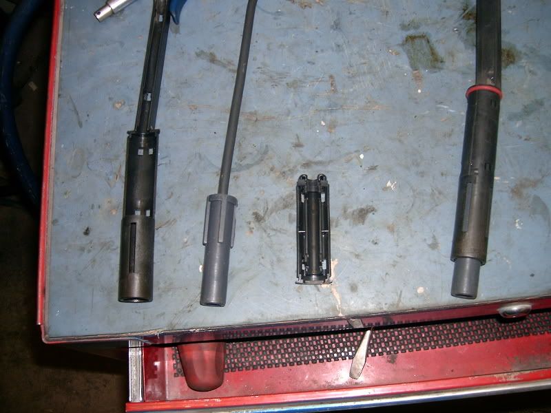
Campairing the stock 96+ boots to the pre 96 boots we can get a length for where we will need to cut the pre 96 boots
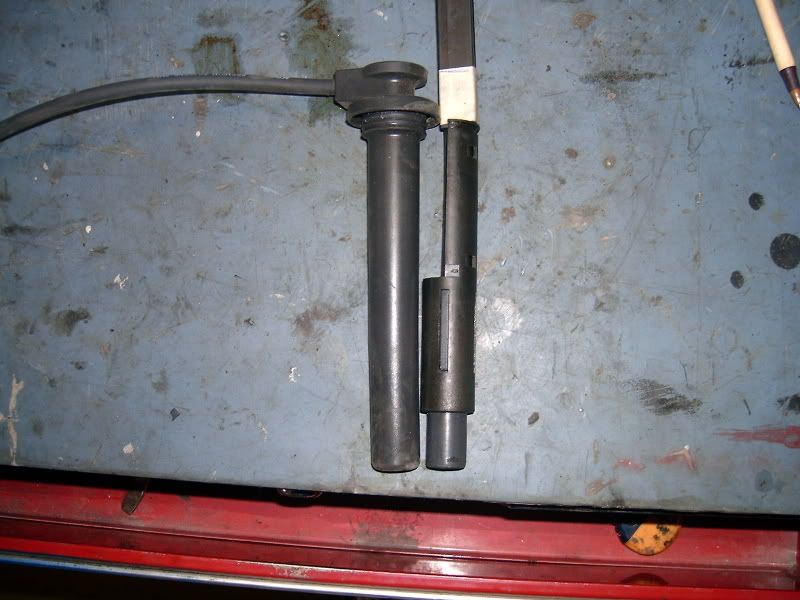
I used masking tape to mark my cut point, then I used a cut off disk on a air tool to cut the length.
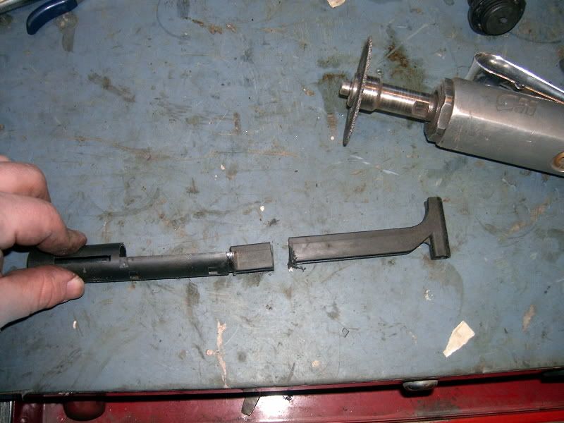
Since we will be needing the tops of the boots to close off the opening I used the factory 96+ boot top. I cut the top off and then used a die grinder to open the wire hole a bit.
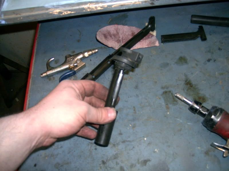
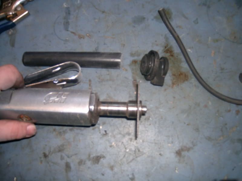
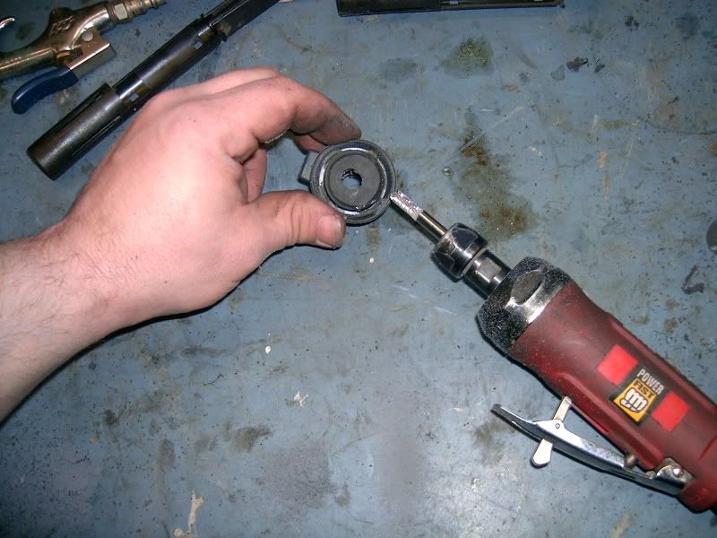
You will need to grind off the excess of the pre 96 tube so that the 96+ Boot Top will go over it.
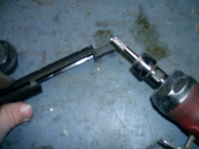
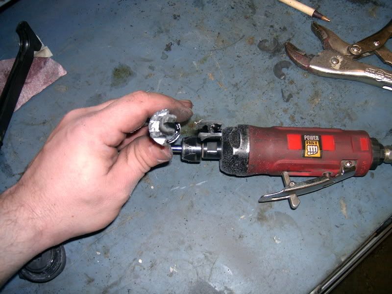
Making the boot that will fit into the Tube.
Placing a new High Temp Boot (8854) beside the factory boot that came out of the pre 96 tube will give us the length to cut the new boot at so that it will fit into the tube.
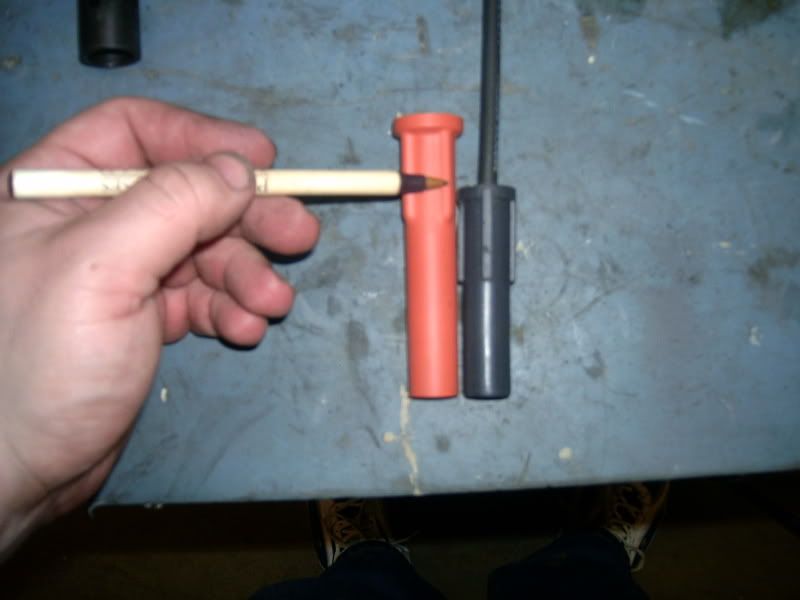
Using a ever sharp knife cut the length.
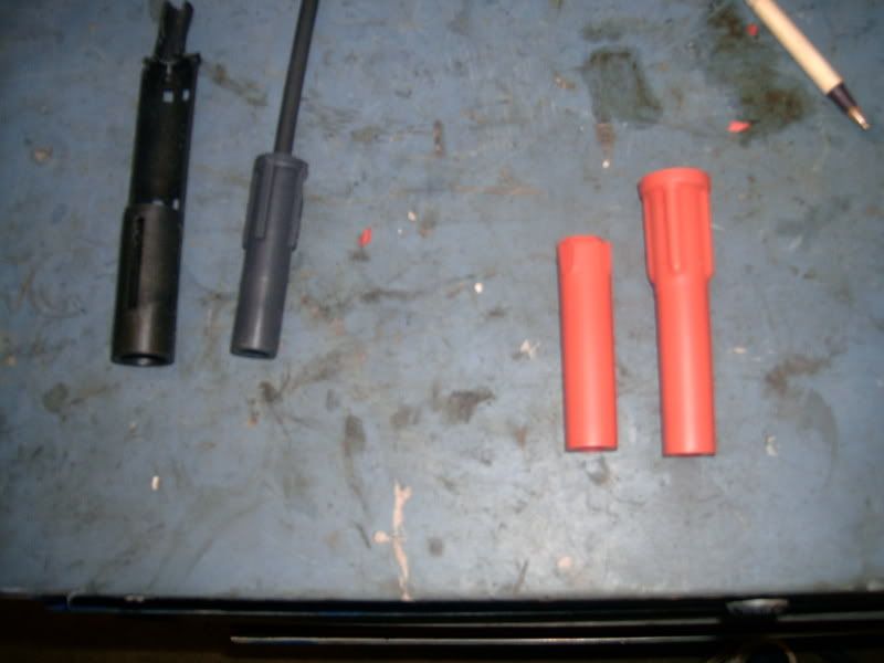
Contantly test fitting the boot into the tube shave down the high temp boot so that it slides into the tube and sits very snug so that it will not slide out then removing the plug wires at a later time.
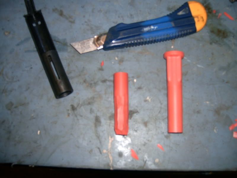
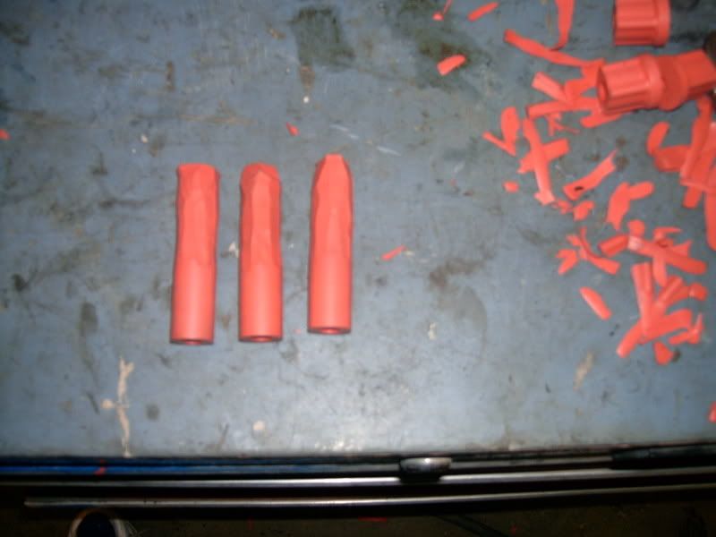
Crimp the end onto an end of wire and then put some Dielectric Greese on the connector and slide it into the high temp boot.
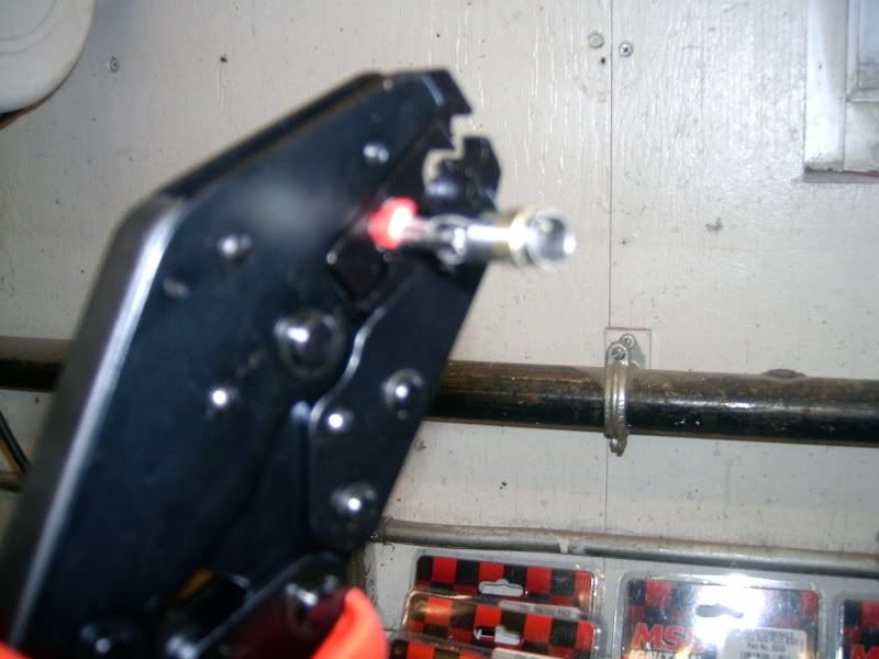
Fit into the tube and re-assmble the factory parts to lock the new boot and wire into the tube.
Test fit the new tube into the plug hole of choice (DO NOT push all the way down)to get the length of wire you will need. Using your crimping tool cut the length of wire.
Now slide the Factory 96+ Boot top down the wire and fit onto the tube top.
Crimp the coil end of the boot and install the boot (8850)
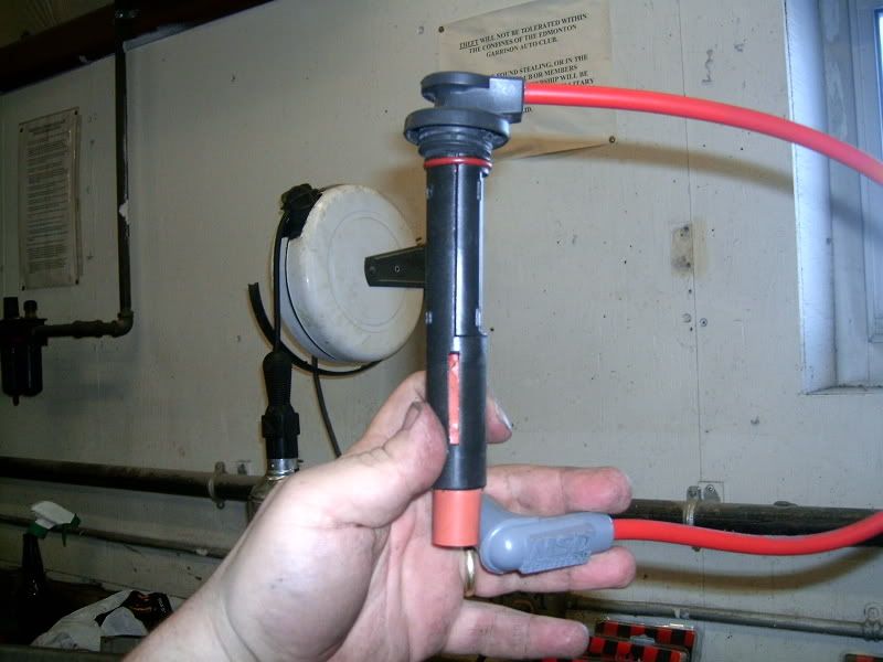
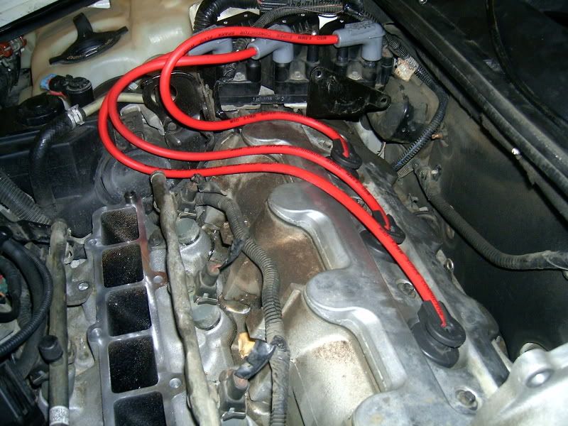
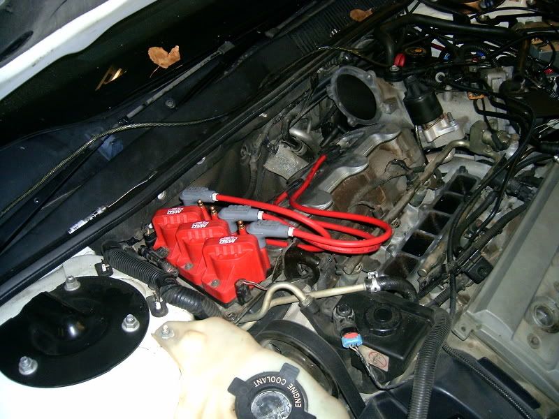
Repeat this proceedure for the remaining two ingnition wires for the rear head.
-------------------------------------------------------------------------------------------------------------------------
STEP 10
Front Head Plug Building
Building of the 3 front wires is similar to the rears except that instead of using the pre 96 tubes you will be using the Hemi Tubes. Not only do these work better but they look a lot better too.
Taking a Hemi-Tube you can see where you will need to grind parts off to get the tube to fit into the plug hole nice and snug.
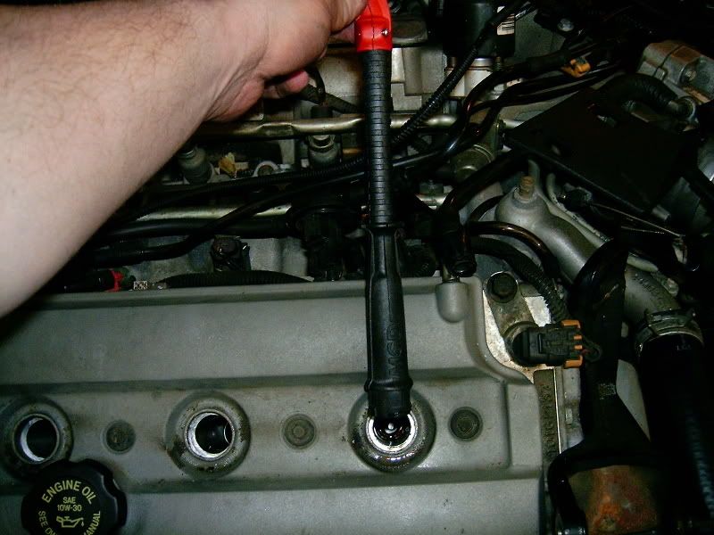
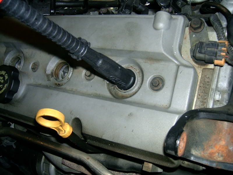
Using a die grinder remove excess and test fit. Continuosly do this until the tube fits into the hole perfectly. Do not remove too much material as you will cut right through the tube.
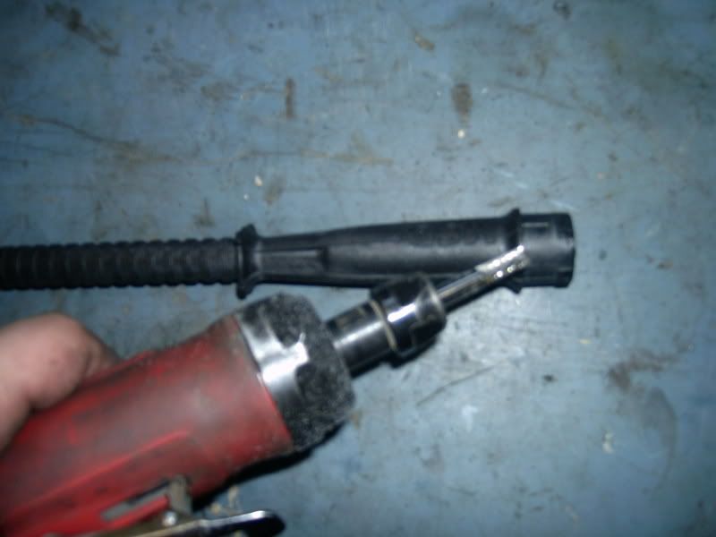
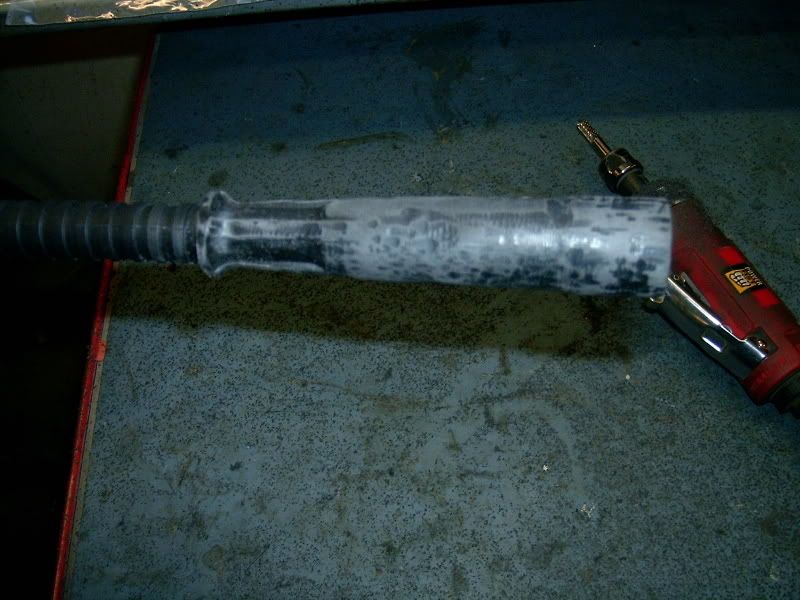
Compared before and after
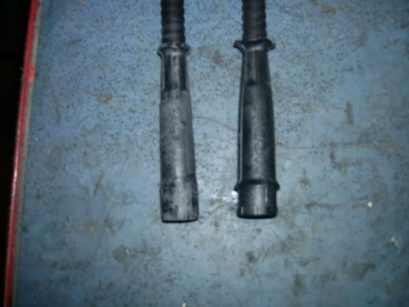
Using a rear plug wire as a reference of length for the High Heat Boot cut and shaving a High Heat Boot (8854) Keep shaving and fitting the boot until it fits perfect and very tight.

Cutting of the wire length is important. Slide an end of wire into the plug hole. Then length the wire to the ICM to get a close estimate length of wire. Add a few inches to account for human error. Set these wires aside.
Going from shortes wire to longest, start assembling the front tubes.
We now need to adjust the height of the Hemi Tube and assemble the wires.
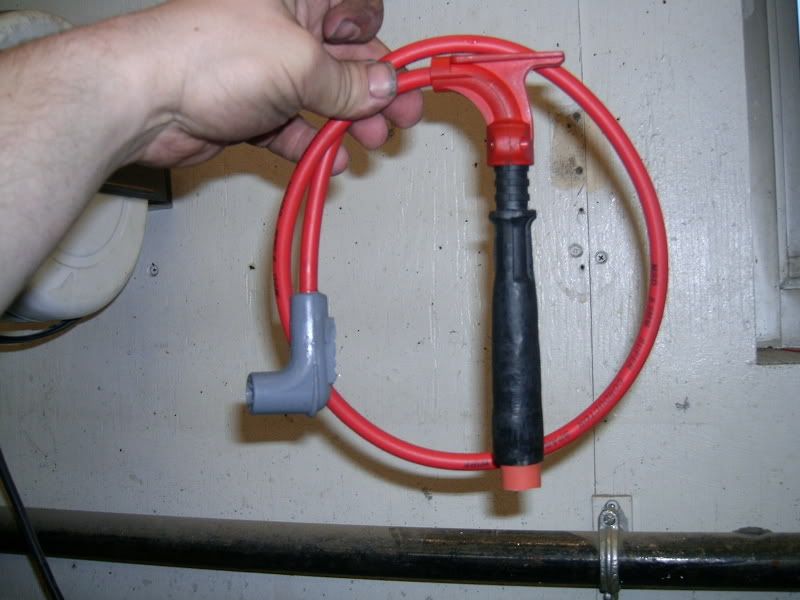
-Crimp a straight connector onto the wire, lube up the connector and slide it into the boot. Now run the wire up the Hemi-Tube forcing the boot into the tube nice and tight.
-Now slide the Hemi-Tube into the plug hole, all the way onto the plug.
-Taking the Red TOp of the Hemi Tube fit it onto the Hemi Tube so that it is close to the opening of the plug hole but not touching the head, giving a few centimeters of space. Mark where the Red Cap goes so that you will now where to cut. If you are unsure, cut long and then refit and then cut again until it fits perfect.
-Remove the Hemi Tube from the head and then remove the wire and boot and begin to clut and fit.
-Once the length of tube is perfect use this marking onto the remaining two tubes.
-Assembly complete now crimp a 90 deg connector and install the 90 deg boot.
-Do this for the remaining two tubes.
STEP 11
UIM Replacement
Now with all the wires cut and fitted and looking good, it is time to replace the UIM.
Following the removal proceedure but only in reverse re-install the UIM.
Get a hold of a torque spec for the bolts and just dont go over tightening the bolts down.
With everything back in place and looking good.
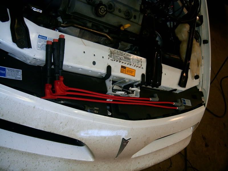
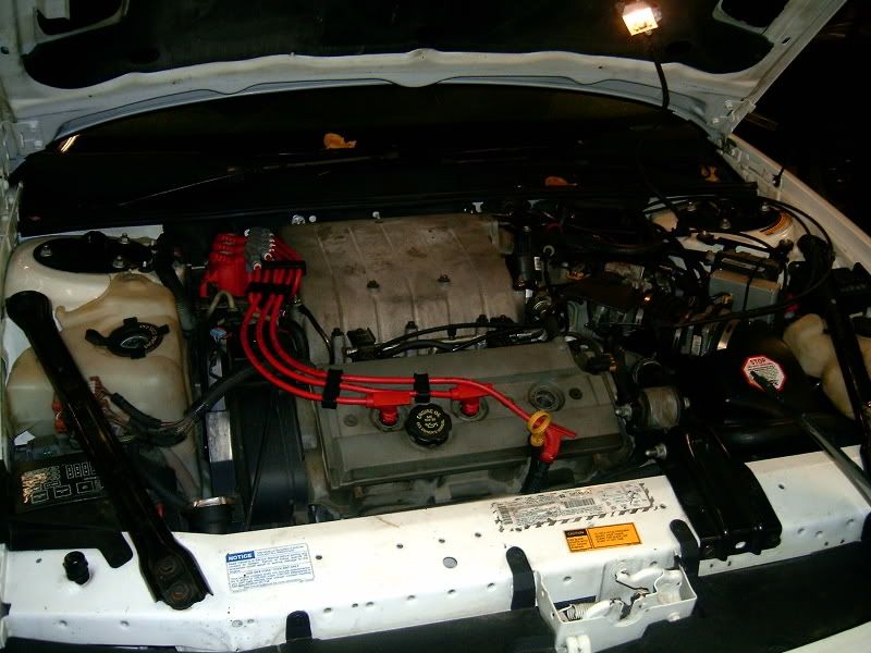
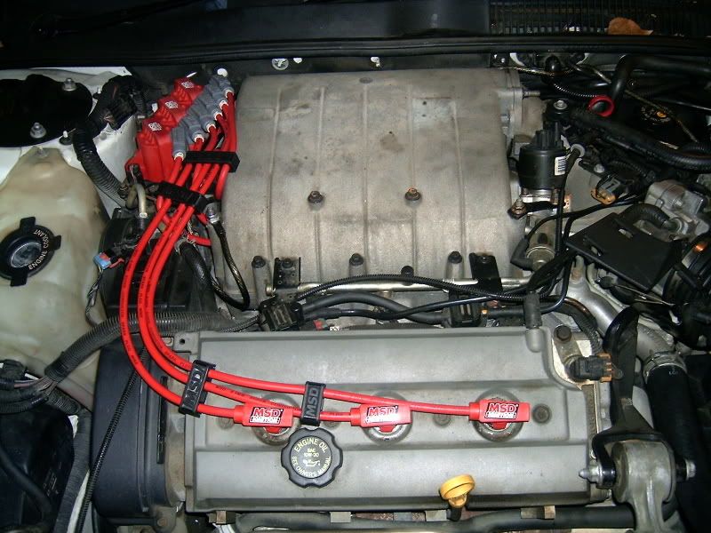
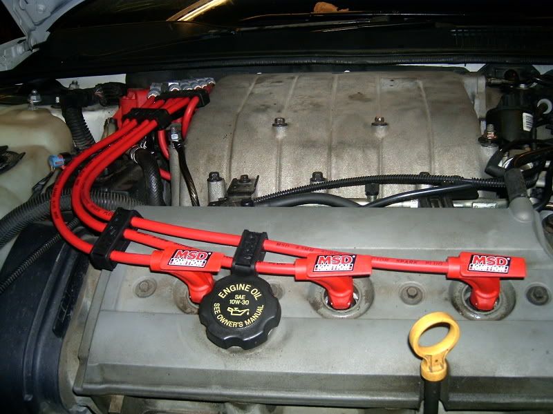
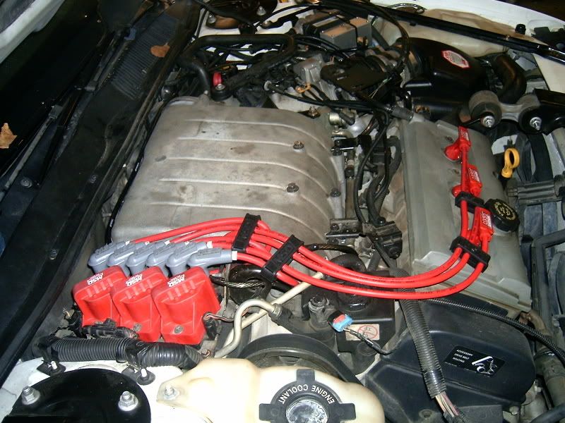
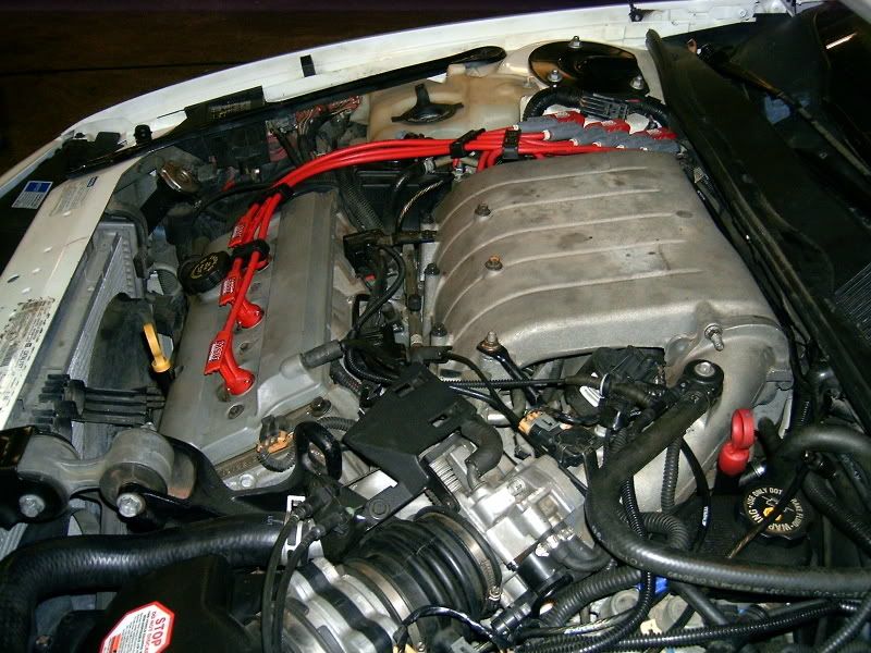
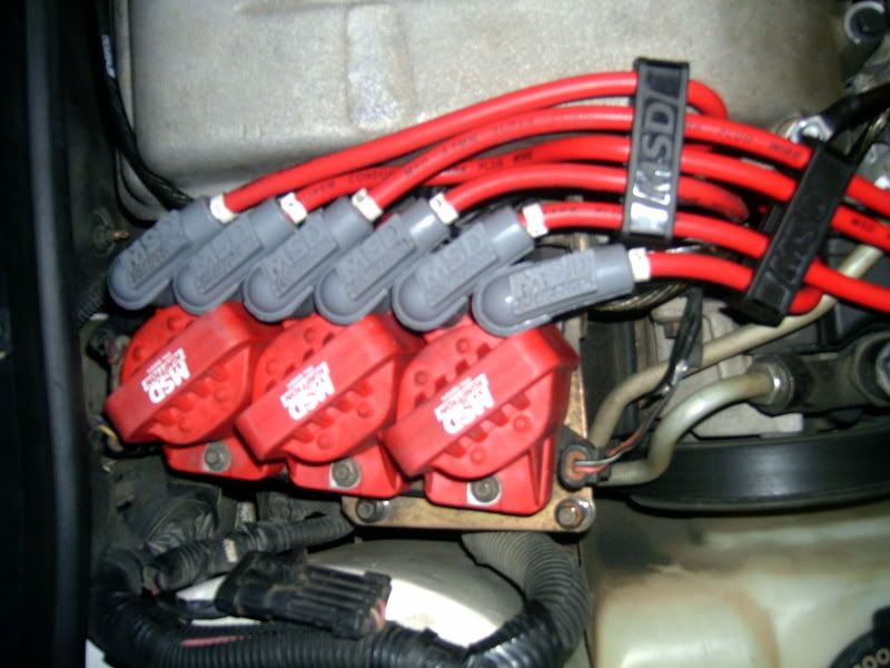
Congrates you have just completed a set of Custom MSD Ignition Wires.
At the writing of the there are currently only Two People that have these made. One is Hayes Performance in Edmonton on his Pre96 GP and mine 96+GP
If you are looking for prices on the parts contact David at Hayes Performance in Edmonton Alberta @ 780-489-7510 or 780-953-7545
Everything you have seen that I used I purchased through David.
I used the MSD parts to create these items.
Here is the list of parts you will need.
MSD 25' 8.5mm Ignition Wire #35019 x1
MSD Ignition Coil #8224 x3
MSD 90Deg Boots/Terminals #8850 x1pkg
MSD High Heat Straight Boots #8854 x1pkg of 8
MSD Hemi-Tubes #3475 x3
MSD Wire Separators #8843 x1pkg
MSD Pro-Crimp Tool #3505
AC Delco Plugs #R42LTSM
GM Gaskets: Throttle Body Gasket, UIM Gasket, Intermediate Intake Tube Gasket
1991-1995 3.4 DOHC Rear Plug Boots or add x3 Hemi Tube Boots for alternate design.
Dielectric Greese


PRE-STEP
Familiarize yourself with how to install a connector onto a piece of wire. Try this several times until you feel confident with how to do this proceedure as it will make a difference with your wires working or not. Use an old wire for reference or talk to someone that knows how and is willing to show you.
STEP 1
Removal of the Upper Intake Manifold(UIM)
The bolts should all be 10mm.
First step is to remove the UIM cause the rear plugs on the 96-97 DOHC are fully covered by the UIM.
There are three bolts on the Intermediate intake pipe to the UIM.

While you are in that area remove the PCV Tube from the UIM. YOu will find it right there by the bolt closest to the firewall.
Now there are (7)Bolts holding down the UIM
There are (2)Bolts holding the Coils to the UIM and
YOu have to remove the EGR bracket held on with (2) Nuts on top of the bolts then you remove #9 Bolt holding down the UIM

Now the UIM will come off, with a little tap with a soft malet and a wiggle it will come off.
I now removed the Ignition Wires once the UIM was off.

STEP 2
TB Gasket Replacement.
IF you are going to be replacing the UIM and Intermediate Gaskets you may as well replace the TB Gasket.
The TB is held on with only Three (3) Bolts. One is on the top of the TB and the other two hold the bracket to the TB going into the intermedate tube. I removed the TB, and cleaned up the mating surface, then reinstalled a NEW gasket (GM) and re-installed the TB. For mating surface cleaning see STEP 4.

STEP 3
Lubricating the Spark Plugs
Since I have no idea when the plugs were last changed I sprayed the plugs down liberally with some liquid wrench and let them sit over night.

STEP 4
Cleaning up Mating Surfaces
Remove all gaskets and clean up the mating surfaces to make sure that there will be no vacume leaks. This is done to the UIM, Intermediate Tube and TB. Where ever there was a gasket going it was cleaned up.
First I used a 2" metal scraper being careful not to gouge the aluminum, then I moved to a air powered grinder with a nylon disk. THe disk is just course enough to remove the old gasket materal and polish the metal but not scrap it.


STEP 5
Spark Plug Cleaning and Gapping
When installing new spark plugs you must always check the gap and give them a little cleaning.
I first started with the cleaning and then gapped the plugs.
I cleaned off both ends with a wire wheel attached to a bench grinder. I then used 100grit sand paper to square off the ends of the electrode and ground for a sharp spark contact.

CLEANED

COMPAIRED

Now gap the plugs.

STEP 6
Spark Plug Removal
To remove the plugs I first tested to see what extensions I would need to get down the long tube. I then very carefully loosened the plugs. Taking note when laying them down to inspect them for any erreularities.


STEP 7
Spark Plug Replacement
Now with the old plugs out, it is time to install the new plugs.
I used anti-seize compound on the threads to help with removal at a later time if need be.
I also recheck the gap just before installation.

STEP 8
Coil Replacement
This step is only for those that are replacing the Coils as well. If you are not replacing the coils please skip this step.
The Ignition COntrol Modual has (3) plugs connected. Remove these.
The coil/ICM is held on with three 8mm bolts to a braket. Remove these bolts so that you can work on the coil/modual on a bench.

Now with the Coil/ICM on the bench we can remove the coils.
The coils are held on with 5.5mm bolts. x2 5.5mm bolts for each coil.


Now the NEW coils can be installed.

Re-install the Coil/ICM first bolting back in place then replacing he plugs.
----------------------------------------------------------------------------------------------------------------------
Now we are into building the Spark Plug Wires.
STEP 9
Rear Head Plug Building
Using the 91-95 3.4 DOHC rear boots we will build the rear plug wires.

These factory boots/tubes separate. There are 4 tabs. Using a pair of needle nose pliers. Once we separate the parts the factory rubber boots can be removed.


Campairing the stock 96+ boots to the pre 96 boots we can get a length for where we will need to cut the pre 96 boots

I used masking tape to mark my cut point, then I used a cut off disk on a air tool to cut the length.

Since we will be needing the tops of the boots to close off the opening I used the factory 96+ boot top. I cut the top off and then used a die grinder to open the wire hole a bit.


You will need to grind off the excess of the pre 96 tube so that the 96+ Boot Top will go over it.


Making the boot that will fit into the Tube.
Placing a new High Temp Boot (8854) beside the factory boot that came out of the pre 96 tube will give us the length to cut the new boot at so that it will fit into the tube.

Using a ever sharp knife cut the length.

Contantly test fitting the boot into the tube shave down the high temp boot so that it slides into the tube and sits very snug so that it will not slide out then removing the plug wires at a later time.


Crimp the end onto an end of wire and then put some Dielectric Greese on the connector and slide it into the high temp boot.

Fit into the tube and re-assmble the factory parts to lock the new boot and wire into the tube.
Test fit the new tube into the plug hole of choice (DO NOT push all the way down)to get the length of wire you will need. Using your crimping tool cut the length of wire.
Now slide the Factory 96+ Boot top down the wire and fit onto the tube top.
Crimp the coil end of the boot and install the boot (8850)

Repeat this proceedure for the remaining two ingnition wires for the rear head.


-------------------------------------------------------------------------------------------------------------------------
STEP 10
Front Head Plug Building
Building of the 3 front wires is similar to the rears except that instead of using the pre 96 tubes you will be using the Hemi Tubes. Not only do these work better but they look a lot better too.
Taking a Hemi-Tube you can see where you will need to grind parts off to get the tube to fit into the plug hole nice and snug.


Using a die grinder remove excess and test fit. Continuosly do this until the tube fits into the hole perfectly. Do not remove too much material as you will cut right through the tube.


Compared before and after

Using a rear plug wire as a reference of length for the High Heat Boot cut and shaving a High Heat Boot (8854) Keep shaving and fitting the boot until it fits perfect and very tight.

Cutting of the wire length is important. Slide an end of wire into the plug hole. Then length the wire to the ICM to get a close estimate length of wire. Add a few inches to account for human error. Set these wires aside.
Going from shortes wire to longest, start assembling the front tubes.
We now need to adjust the height of the Hemi Tube and assemble the wires.
-Crimp a straight connector onto the wire, lube up the connector and slide it into the boot. Now run the wire up the Hemi-Tube forcing the boot into the tube nice and tight.
-Now slide the Hemi-Tube into the plug hole, all the way onto the plug.
-Taking the Red TOp of the Hemi Tube fit it onto the Hemi Tube so that it is close to the opening of the plug hole but not touching the head, giving a few centimeters of space. Mark where the Red Cap goes so that you will now where to cut. If you are unsure, cut long and then refit and then cut again until it fits perfect.
-Remove the Hemi Tube from the head and then remove the wire and boot and begin to clut and fit.
-Once the length of tube is perfect use this marking onto the remaining two tubes.
-Assembly complete now crimp a 90 deg connector and install the 90 deg boot.
-Do this for the remaining two tubes.

STEP 11
UIM Replacement
Now with all the wires cut and fitted and looking good, it is time to replace the UIM.
Following the removal proceedure but only in reverse re-install the UIM.
Get a hold of a torque spec for the bolts and just dont go over tightening the bolts down.
With everything back in place and looking good.


Congrates you have just completed a set of Custom MSD Ignition Wires.
At the writing of the there are currently only Two People that have these made. One is Hayes Performance in Edmonton on his Pre96 GP and mine 96+GP
If you are looking for prices on the parts contact David at Hayes Performance in Edmonton Alberta @ 780-489-7510 or 780-953-7545
Everything you have seen that I used I purchased through David.


Comment